Thursday 29 December 2016

BlueFlyVario_Bluetooth_USB_v12 model almost ready

Early in the new year I will begin shipping the new BlueFlyVario Bluetooth_USB_v12 model. You can pre-order from today, but shipping will not commence until mid Jan 2017 when I have completed production of the first batch. In this short blog post I will describe what to expect from the new model. A more comprehensive post will accompany the first shipments which will describe assembly and configuration.


New Features

The v12 model is an evolution of the v11. The main change is the addition of a USB data connection on the same board as Bluetooth, but there are many other little changes:

  • The V12 adds a FT230x USB-serial chip to the board to allow the USB connector to be used for more than just charging. This will simplify adjusting settings using Windows, and allow for a wider range of compatibility. This feature included adding an analog switch to manage when UART data is sent via Bluetooth and USB. It works like this:
    • If Bluetooth is not connected data is only sent and received from the Bluefly via the USB-serial chip. 
    • If Bluetooth is connected then data is sent to both the Bluetooth and USB-serial connection, but only received from devices connected via the Bluetooth connection.
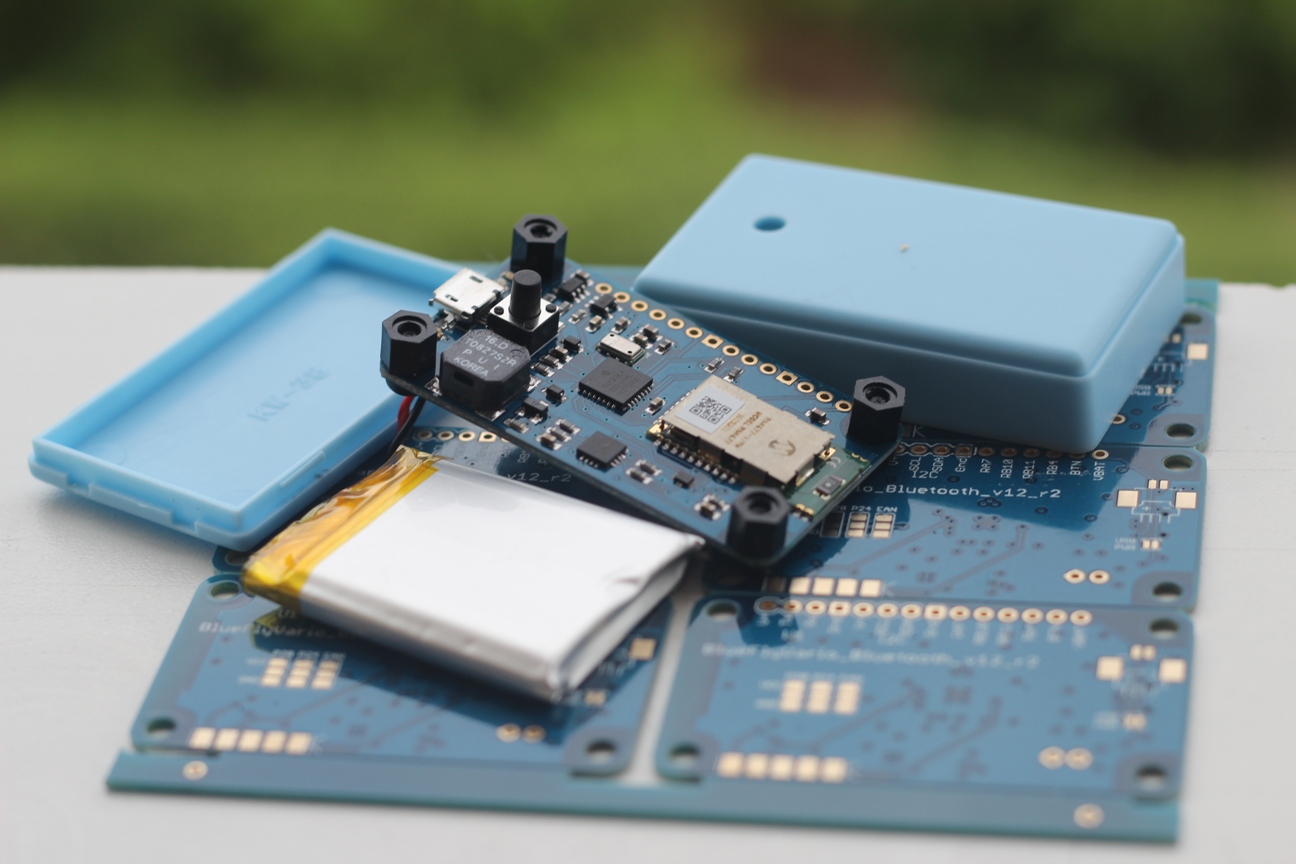
  • The V12 board was lengthened by a few mm to allow for the extra space needed for the new components. It now takes up almost the complete length of the case. 
  • Power consumption is reduced by about 30% when not connected via Bluetooth. This was achieved by changing the way the RN4677 Bluetooth Module is disabled after the bluetoothSecondsWait timeout. 
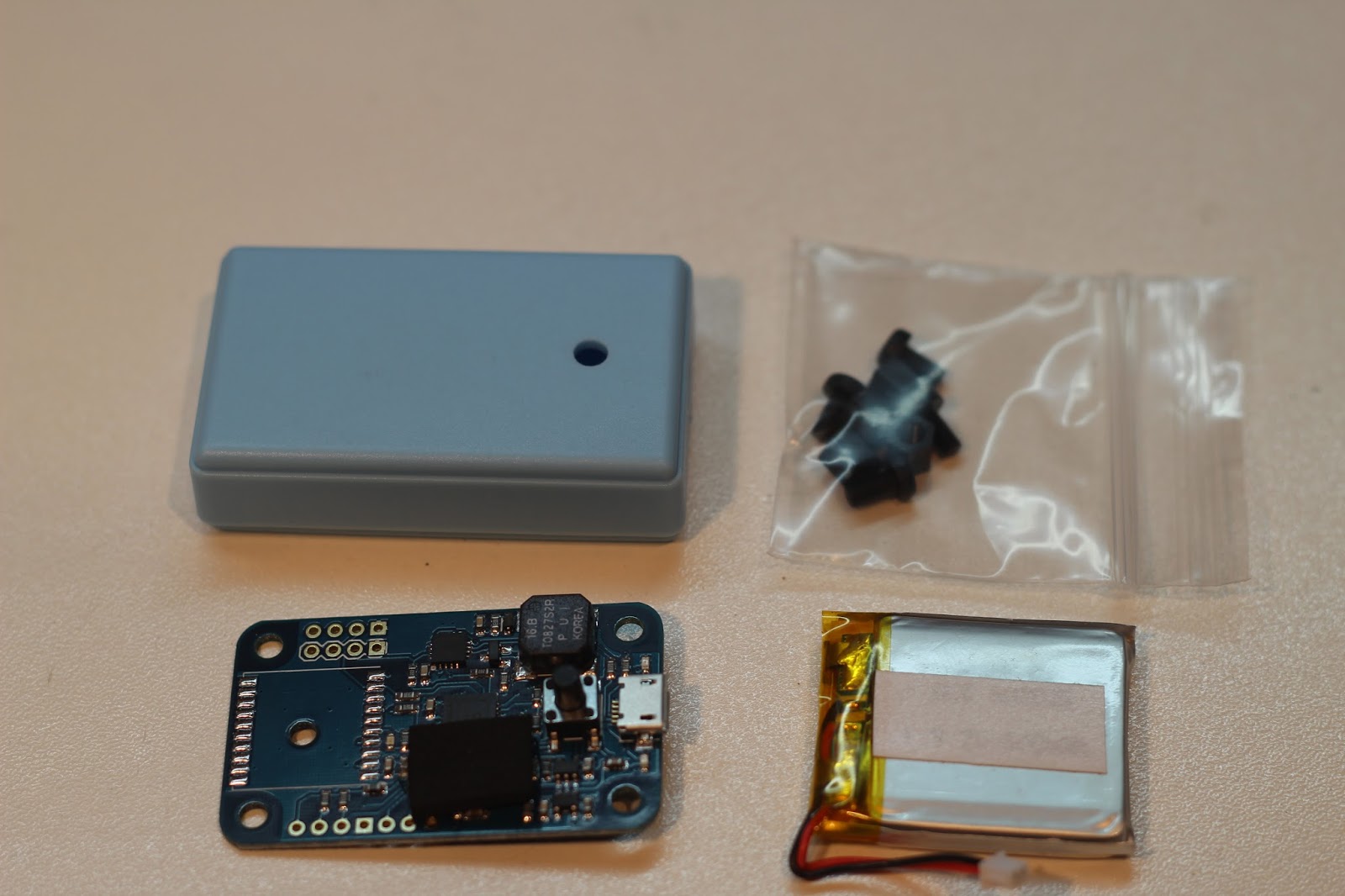
  • The battery will be upgraded from 600mAh to 750mAh, taking up all of the spare space in the case. This makes for a snug fit and reduces the need for packing. 
  • The LED's have all been moved near the USB connector. 
  • The speaker has been rotated by 90 degrees, which will allow a small hole to be drilled in the side of the case if you really want to maximize the volume. 
  • All spare pins from the micro-controller, the button, battery voltage, etc are now all exposed in one row of headers. This will simplify hacking and will allow for things like an analog voltage input to be sensed. 

What stays the same

  • The case and standoffs are the same as the v11, as is the micro-controller, pressure sensor, RN4677 Bluetooth module, and supporting components. 
  • All of the hardware settings options, although I will be changing the defaults to the most common settings
  • The price, almost... I had to add a few dollars to take into account the cost of the FT230x USB chip and new analog switch. 

Other Models

  • The BlueFlyVario_Bluetooth_USB_v12 will will replace the BlueFlyVario_Bluetooth_v11. The v11 model is now almost out of stock and I am no longer accepting orders for it.
  • The BlueFlyVario_TTL_GPS_v11 remains the current model for connecting to a Kobo via TTL. I am some months away from considering what updates I will do to that model. The main change in v12 - the addition of USB to the Bluetooth model, is not applicable to the TTL model. 
  • The BlueFlyVario_USB_v11 and BlueFlyVario_USB_GPS_v11 remain current if you do not need a Bluetooth connection. 
  • The v11 shields are still available, and are electrically compatible with the v12, but the pins do not exactly match the new headers.


Sunday 30 October 2016

New Firmware with Audio Settings updates

This is a quick post to let you know about two new features in the latest firmware released today. You can download the latest version of the firmware from http://www.blueflyvario.com/firmware/.

Audio toggle

After you have turned the vario on with a short press on the button it starts making noise. The vario noises can be turned off by adjusting some of the audio hardware settings, however for many pilots they just want the vario to be quiet until they launch (but still send data to the phone or other device it is connected to). For some time you have been able short press on the button to toggle between silence and noise. A long press turned it off.

With the new feature added in firmware version 11.m13 a short press on the button toggles between 'Audio Off' >> 'Audio On' >> 'Audio Off'.

However, if you have useAudioBuzzer enabled then it toggles between 'Audio Off' >> 'Vario Audio On only' >> 'Vario Audio and Buzzer On' >> 'Audio Off'.

Auto toggle on

In conjunction with the updated audio toggle feature, there is a new feature which automatically toggles the audio back on when lift or sink is greater than the toggleThreshold. This new hardware setting (BTT) means that you can turn the vario on with a short press. Then toggle the audio off (with another short press), then when your flight begins, indicated by lift or sink being greater than toggleThreshold, then the audio will toggle back on.

Manual and BFVDesktop

In conjunction with these features I have updated the hardware settings manual, and the BFVDesktop application

Monday 29 August 2016

Force Bluetooth SPP Mode

Yesterday I posted about a firmware update with a new hardware command for adjusting settings on the RN4677 bluetooth module. Today I will tell you how to use this new command to force the RN4677 to use Bluetooth SPP mode. This was motivated by getting the BlueFlyVario_Bluetooth_v11 to work with some Android devices (like the WayteQ x995). The procedures described here will also help with some apps (FlyMe and XCTrack).

Some background

The RN4677 bluetooth module from Microchip included on the BlueFlyVario_Bluetooth_v11 is a very capable device. You can find a comprehensive user guide here: http://www.microchip.com/wwwproducts/en/RN4677. This module allows the BlueFly to connect to iOS devices using Bluetooth Low Energy (otherwise known as BLE, or Bluetooth 4.0), while also being able to connect to a very wide variety of Android and Windows PC Bluetooth adapters using Bluetooth Simple Port Protocol (otherwise known as SPP, which is available on Bluetooth 2.0 or 2.1 devices).


A full description of how these protocols work is beyond the scope of this post. However, it is sufficient to say that if your Android device supports BLE (most new devices) and SPP (almost all devices), then it is possible that an Android app might try to connect to the BlueFly over BLE. If that happens then the connection will probably fail. So far, I do not think that there are any Android apps which have BLE working with the BlueFly. It is something which is on my todo list for the BlueFlyVario app.

Step 1: Connect to the BFVDesktop application

The first step is to get your BlueFly connected to the BFVDesktop application (download from here) via a PC with a Bluetooth adapter. If your Bluetooth adapter supports BLE and you can not seem to avoid it then you can force a non BLE connection by disabling part of the driver. A quick way to do this is to open Device Manager and disable 'Microsoft Bluetooth LE Enumerator' in the Bluetooth section. Make sure to remove the BlueFly device, then add it again and complete the pairing process. Use the paired virtual serial port in the BFVDesktop application. You should see the data streaming in.

Step 2: Make sure you can communicate with the BlueFly 

Send a few test commands using 'Raw Tx:' Try $BTN* to simulate button presses. You should hear beeps.

Step 3: Adjust settings on the RN4677

Send the command $RNC SG,2*

Note the space between RNC and SG. When you send this command the BlueFly does the following:
  • Puts the RN4677 module into command mode (by sending $$$ from the processor the the RN4677); this kills the connection. 
  • Sends the RN4677 the SG,2 command (see page 17 here: http://ww1.microchip.com/downloads/en/DeviceDoc/50002377A.pdf - You can use the RNC command to the Bluefly to progressively send any series of set commands the RN4677; but be careful unless you know what you are doing)
  • Sends the RN4611 the command R,1; which resets it and stores the setting
  • Restarts the BlueFly
Step 4: Restart everything

You will then need to restart the BFVDesktop app to connect again. Unfortunately, there is no easy way to check the settings on the RN4677 unless you have a TTL-Serial adapter and can solder it in between the processor and the RN4677.

After that, un-pair the BlueFly from your Android device, restart the device and the BlueFly, and then try paring and connecting again. XCTrack and FlyMe should now work!

Further Steps

If that does not work you might also want to try further configuring the RN4677 authentication modes. On some devices that affects how they connect after pairing:
  • $RNC SA,1* will change the RN4677 from 'SSP just works' mode to 'SSP pin code confirm mode.
  • $RNC SA,4* will change the RN4677 to legacy 4 digit pin mode. The default pin is 1234.
There are many other settings you can mess with (and mess up) on the RN4677. If you really screw it up please contact me. 

Saturday 27 August 2016

Firmware update for v11 models

Last weekend I was able to release a new firmware for the v11 models of the BlueFly. The v11 models have a different processor (the PIC24F32KA302 instead of the PIC24F32KA301) which uses different pins for most of the hardware functions. As a consequence there is a slightly different bootloader on the vario, although you do use the same ds30loader program on the PC side.

Firmware updates for BlueFlyVario started with v10, and you can still download the latest firmware for the v10 models from the firmware page of the website. For the v10 models you should follow the instructions in this previous blog post.

Do I need to update the firmware?

If you are happy with the performance of the BlueFly, and you do not need any of the features of the new firmware, then I strongly urge you to leave it alone. Although it only takes me a minute or two, many pilots find it tricky. If you are going to do it then the first step is to check what firmware you currently have.

The firmware for the initial release of the Bluetooth, TTL_GPS and USB models was 11.M09, 11.M10, and 11.M11 respectively. Although I only released the 11.M12 firmware last weekend, I have actually been shipping it with new varios for some weeks. You can see what version of the firmware your device has by using the BFVDesktop app and connecting to your device. That will be tricky if your TTL_GPS model is soldered to the Kobo. For that model try starting up the vario while you are looking at the monitor in xcsoar and read the message from the BlueFly. The first line includes the firmware version.

Key changes in 11.M12

The primary reason for releasing a new verison of the firmware is to support some changes for the Bluetooth model, although there are some other changes as well. In summary the changes are:
  • A new command designed which enables you to change settings on the RN4677 blueotooth model. Read the hardware settings manual to understand how to send a command. The command is:
    • $RNC ABC*, where ABC is the command to send to the RN4677. 
    • When you send that command to the BlueFly it sends back some serial signals to the RN4677 in the following manner:
      • Turns on the BlueFly green LED.
      • Sends $$$ to the RN4677, which puts it into command mode. This stops the BlueFly sending data. 
      • Waits 1000 ms.
      • Sends ABC to the RN4677 followed by the \n character. In most cases ABC is an individual RN4677 command you choose from it's user guide to adjust a setting on the module 
      • Waits 500 ms. 
      • Sends R,1\n to the RN4677 to restart the RN4677 and store the setting.  
      • Waits 500 ms. 
      • Turns of the BlueFly green LED. 
      • Restarts the BlueFly. 
    • It is really possible to screw up the RN4677 by doing this if you are not sure what you are doing. I will be posting some examples in a separate blog post. 
  • The new firmware maintains the volume of start and shutdown beep, regardless of the volume settings.
  • The RSX command now also sends $PMTK104*37 to U1. On the TTL_GPS model that forces the GPS to ditch its ephemeris data (satellite data) and restart. This can be used to recover a GPS which may be stuck in some kind of bad data loop. 
Bootloader changes

There are minor changes to the bootloader procedure for the v11 models. The procedures described in this previous blog post for the v10 still apply, but with the following changes:
  • Step 1 - Get the software: No change, the same ds30loader software is used. 
  • Step 2 - Prepare the hardware: On the v11 you now short the pins below (GND and SDA) to enter the bootloader mode. The names of these pins are shown on the bottom of the board. 


  • Step 3 - Open the ds30laoder application: Use the following different settings for v11, all of the others are the same as v10
    • Model: 32KA302
    • Baud: 115200
  • Step 4 - Start up the Bluefly in bootloader mode: No change; other than the different pins as shown above in step 2. 
  • Step 5 - Program the device: No change
Hardware Settings Reset

After updating the firmware I recommend that you execute a full hardware settings reset. On the v11 models you do that by shorting GND and SCL then starting the vario while the short is in place. Once you hear the high pitched fast beeps you can release the short and all of the settings will be back to the defaults.

TTL_GPS model addendum for the Kobo

Tyson let me know he has been working on updating the firmware on the BlueFlyVario_TTL_GPS with it still connected to the Kobo. In his words:

"Thought you might be interested in this small program I wrote. Converts the hex files into a shell script that can be directly run on the kobo to do the flash upgrade.

https://github.com/twhitehead/blueflyvario-hex2sh

Just finished using it to upgrade to the latest firmware for my BlueFlyVario_TTL_GPS_v10 model. Seemed to go good."

I am still waiting to find time to try it out. Let me know how much success you have.


Monday 22 August 2016

BlueFlyVario_TTL_GPS_v11 component updates

This quick post describes a minor modification to the package contents with the BlueFlyVario_TTL_GPS_v11. The package now includes:
  • The BlueFlyVario_TTL_GPS_v11 main board programmed with the latest firmware.
  • A small piece of neoprene to protect the sensor.
  • 50mm of blue PVC heatshrink.
  • About 20cm of 4 core flat telephone cable.
There is also a slight change to the component layout on the most recent PCBs to allow for easier manufacture. The Rev 4 PCB layout has much more evenly spaced components, and is shown below with the components now included in the package.


Cable

The 4 core flat telephone cable included with the package is much more appropriate for soldering inside the Kobo. Strip the outer covering and use the wires individually. I used this type of cable on the Kobo Glo HD Install shown in this previous blog post. If you really want the 4x1P right angled header and 4x1P Dupont connector with wires please let me know when you order and I can include it in the package. 


Neoprene

The little piece of neoprene included with BlueFlyVario_TTL_GPS is really important. When placed properly it stops light from hitting the sensor, but allows air to permeate through so pressure changes filter through the two little holes on top of the MS5611 pressure sensor. 
  • I originally include the neoprene shown below. This has sticky tape on one side, and black squishy foam on the other. Unfortunately some pilots remove the sticky tape and put it on the sensor the wrong way; blocking the two little holes with the sticky glue and rendering the sensor pretty much useless. 
  • So, then I changed to different neoprene which does not have sticky tape on it so it does not matter which way it is placed on. Unfortunately it was a slightly different composition, and when that neoprene is squished on to the sensor really tight with the heatshrink it can restrict the airflow associated with pressure changes; to the extent that it affects the sensitivity of the vario to changing height. If you have this neoprene and it is not working for you please let me know and I can ship you some of the other stuff. 
  • Now I have changed back to supplying the original type of neoprene. The correct orientation is shown in the image below. The black squishy foam side should be the only thing which touches the sensor. Please put it on the right way!


Sunday 14 August 2016

New BlueFly USB models released

I am pleased to release two new USB models of the BlueFly today. These models complement the Bluetooth and TTL_GPS models by providing devices which can connect via USB. Both are available for purchase on the new website http://blueflyvario.com/shop. This post is pretty long as there are many different ways you can use these two new varios.

Which BlueFly vario do you want? Choose between:
  • The Bluetooth model to connect to Android or iOS for use with flight apps.
  • The TTL_GPS model to solder to a Kobo or other device with a TTL Serial port.
  • The USB model as a stand alone audio vario; or for connection to USB ports on many devices.
  • The USB_GPS model for a wired connection to a Kobo or other device with a USB port, but without an inbuilt GPS.
BlueFlyVario_USB_v11

The new USB model is designed for use as a stand alone audio vario. In many ways it is similar to the BlueFlyVario_USB_v10. However, it now shares the more powerful battery and enclosed sky blue case as the Bluetooth model. In some ways it is a cheaper version of the Bluetooth model with a FTDI FT230X USB to serial chip instead of the more expensive Bluetooth module.


The package includes the items shown above:
  • BlueFlyVario_USB_v11 main board programmed with the latest firmware, and with a small piece of neoprene protecting the sensor.
  • 600 mAh Lithium Polymer battery.
  • 4 x 5mm nylon M3 hex standoffs and 4 x 6mm M3 nylon screws.
  • The skyblue BlueFly case.
To assemble the vario use the same procedure as the BlueFlyVario_Bluetooth_v11. The battery on the USB model should last much longer than 10 hours. The actual duration will depend on your audio settings. Charge it with a phone charger with a micro USB connection, or by connecting it to a USB port. 

For advanced users the BlueFlyVario_USB_v11 is the most hackable model yet:
  • It is compatible with the same shields as the Bluetooth_v11 model. 
  • The button and speaker both have headers underneath them if you want to remove either and wire in other components. 
  • On the PCB U2 is connected to the FT230X chip (which is then connected to the USB port), but there are exposed headers if you want to plug U2 directly into a TTL connection. 
  • You can close SJ1 if you want to power the vario directly from the USB power instead of the battery. Do not close this jumper if the battery is still connected or it will get uncontrolled voltage to the battery and it may be damaged.
  • U1 is exposed for shields or to connect to another UART device which sends NMEA strings. There is space on the USB model for a PA6H GPS, which brings us to the next model.  
  • You can close SJ2 if you want to connect VBackup of the GPS to the battery power (for the model shown below).


BlueFlyVario_USB_GPS_v11

The USB_GPS model is exactly the same circuit board as the USB model, however it has a PA6H GPS soldered in place. If you are just going to use the vario as a stand alone audio vario then the GPS adds no value. However, if you want to make a wired USB connection to an Android or Windows device which does not already have a GPS, or you want to connect to the USB port of some models of the Kobo, then this might be the vario for you. 


Note that I have not tested the USB_GPS model with a wide variety of devices. If you are considering using this vario please make sure that your device has an operating system which can access the serial output from FTDI based chips, and that xcsoar or whatever app you are going to use can find that serial output in the operating system. 

Connecting to PC

If you have either of the USB models you will probably want to connect it to a PC to adjust some hardware settings. When you connect it with a standard USB cable your PC should install the appropriate FTDI drivers in Windows 7 and 10. Use the BFVDesktop application (available in the software section of the support page) to connect to the installed serial port. 

Connecting to Android

To connect to Android you will need a USB-OTG cable and Android 4.0 or later. See the image below for an example of the connection required. You will probably use a procedure similar to that described in this blog post. You might also want to use the FTDI UART Terminal app to test the connection or send Hardware Settings as described in Annex A of the manual. That app is shown in the image below; make sure to set the baud rate at 57600. 


Connecting to Kobo with xcsoar

Establishing a connection to the Kobo USB port with the FT230X chip in the USB models is a little more involved. 
  1. First you need to modify the USB PID on the BlueFly FT230X chip. The standard PID on the FT230X is '6015'. This PID is not recognized by the standard ftdi_sio driver on the modified Kobo kernel. If you modify it to the PID associated with the FT232 chip ('6001'), then FTDI drivers work appropriately. This step is achieved by using the FT_PROG EEPROM Programming Utility from FTDI on a Windows PC. With your BlueFly connected you will 'Scan and Parse' to find the FT230X chip. Then navigate to 'USB Device Descriptor'|'VID PID', select 'Custom PID' in the drop down, change the PID from 6015 to 6001, then 'Program Devices' to write that to the BlueFly FT230X. 
  2. You need a USB OTG Y cable as shown below. The UART chip in the Kobo needs external power to work (the BlueFly does not provide it). This will work best if the BlueFly and Kobo are fully charged. If not, the external power pack will be quickly drained as both the Kobo and the BlueFly are charged from it.
  3. After you have installed xcsoar on your kobo you need to enable USB-OTG from the System menu at the start up screen. This will reboot the kobo and make its linux use a different kernel which has the ftdi_sio drivers. I have tested this step with the Kobo Mini and the Kobo Glo HD with xcsoar version 6.8.6. 
  4. In xcsoar navigate to Menu|Config|Devices|Edit, change the port to ttyUSB0, baud 57600, driver BlueFly. After clicking ok you might have to Disable and Enable a few times. Click the Monitor to see the data stream. 

If you connect the USB models to other devices please contact me and I will update this post. 

Wednesday 20 July 2016

Kobo Glo HD Install

The BlueFlyVario_TTL_GPS_v11 installed in a Kobo Glo HD is a great combination. This post has taken a while to put together as a little bug was worked out of XCSoar by the developers. Most of the install procedure is the same as with other Kobo models and earlier versions of the Bluefly. In this post you can read how to put it all together. You should also read earlier posts about the BlueFly and Kobo:

http://blueflyvario.blogspot.com.au/2016/04/blueflyvariottlgpsv11-released.html
http://blueflyvario.blogspot.com.au/2015/08/more-bluefly-and-xcsoar-integration.html
http://blueflyvario.blogspot.com.au/2015/06/ttlgps-support-tips.html
http://blueflyvario.blogspot.com.au/2015/03/blueflyvariottlgpsv10-improvements.html
http://blueflyvario.blogspot.com.au/2014/11/kobo-glo-install.html
http://blueflyvario.blogspot.com.au/2014/07/blueflyvariottlgps-simple-case.html
http://blueflyvario.blogspot.com.au/2014/04/blueflyvariottl-integration-with-kobo.html

What you will need

Gather the following things:
  • BlueFlyVario_TTL_GPS_v11 module. You will not need the header, wires or Dupont connector that comes with it; but you will need the small piece of neoprene, and some of the heatshink. 
  • Some smaller wires. I think the wires from a small piece of 4 core telephone cable are just right. 
  • A Kobo Glo HD. 
  • A Bluefly Kobo Glo HD Simple Case, you can download this case from Thingverse. Find a friend with a 3d printer or order a copy from an online 3d printing service.
  • Some double sided tape and superglue.
  • A good soldering iron and some skill using it. 
  • A sharp knife. 
Step 1 - Set up XCSoar on the Kobo

This procedure starts pretty much the same as earlier installs. Get the Kobo, make sure it works as a standard eReader, then remove the back cover and back up the internal SD card. Note the back cover of the Glo HD pops off by running around the edge with your fingernail. After the SD Card is backed up install XCSoar as described on the XCSoar download page. When XCSoar is working power off the Kobo.

Note that you should make sure you install XCSoar version 6.8.5 or later. That version fixed a small bug which affected the performance of the display in earlier versions when there were rapid vario data updates. 

Step 2 - Solder the BlueFly module to the Kobo

Start by soldering the four thin wires to jumper J4 at the top right hand side of the circuit board. Do not be tempted to use one of the other ports; they do not work. Most people will not have much trouble soldering in Tx, Rx, and V, however you will probably find GND difficult as it needs more heat. Don't use too much or you will damage the board.


The wires are then routed out the side of the case. You should use a sharp knife to make the appropriate holes in the bezel and the back.

Attach the BlueFlyVario_TTL_GPS_v11 module to the wires. Make sure to solder V to V, GND to GND, KoboTx to BlueFlyRx and KoboRx to BlueFlyTx. The image below shows the BlueFly module attached with the wires so that there is about 2mm between the edge of the Kobo bezel and the BlueFly module. Ignore the hole in the top of the bezel; that is from earlier experiments. 


Step 3 - Install the  Case

The case file is printed as a single object. The image below shows the file printed in blue abs on a pretty rough 3d printer.

The part on the left breaks off and is the lid of the case. 

Add the neoprene to the pressure sensor:

Then secure it with a little of the heatshink.

The main part of case fits under the bezel and the BlueFly fits in it (this image was before I soldered the wires so I could get the length right)

Fix the case to the Kobo with a few bits of double sided tape underneath and along the side. If you are super confident you might want to glue it, but I found that the double sided tape was good enough. Also use some double sided tape between the bezel and the lid. To finish the install glue the lid to the case with superglue. In the image below I just fixed it with some tape.

Step 4 - BlueFly Configuration

Configure XCSoar by adding the BlueFly in the devices menu. Initially use the BlueFlyVario driver and make sure you set the baud rate at 57600. Check the monitor to see data streaming in from the BlueFly.

Next install this BlueFlyMenu.xci file using the procedure described in this earlier post. This file adds a few menu options. Use the LXMode button to send a few commands to the BlueFly to change the output mode and rate, then adjust the driver to the LXNav driver. Check out some of the other commands by inspecting the xci file in a text editor. Alter the file to adjust other hardware settings described in Annex A to the Hardware Settings Manual.

Using It

XCSoar is very powerful and has many options. Fly safe!


Monday 2 May 2016

BlueFlyVario_Bluetooth_v11 Sky Blue Case Install

Last week I was happy to announce a new sky blue enclosed case for the Blueflyvario. All orders for the BlueFlyVario_Bluetoooth_v11 will now ship with the new case, and from today it is also available for separate purchase.  In this post I will describe the standard install method for this new case. This replaces the video posted over a year ago which described the install method for the previous acrylic prototype case. 

What is in the bag?

The images below shows the bag you get and what is inside it:
  • The BlueFlyVario_Bluetooth_v11 module. The modules shipped with the sky blue case are a little different from earlier versions:
    • There is a small piece of neoprene glued to the side of the pressure sensor. This is really important from stopping light on the pressure sensor, do not remove it. 
    • The button is 8mm high instead of 9mm. If you are using an older module with a upgraded case you might want to reduce the button height with a file, although it does not really matter. 
    • There is no heatshrink. 
  • A 600mAh single cell LiPo battery. 
  • 4 x 5mm M3 black nylon hex stand offs and 4 x 5mm black nylon M3 screws. 
  • The sky blue case base with cut outs and the sky blue case top. To remove the top you will need a small screwdriver to gently pry it off by twisting the screwdriver gently in the gaps.


Install Step 1 (Optional)

The first step is only needed if you want to put a small lanyard on the vario. Drill a couple of holes into the case at the opposite end from the USB cutout. Use a slow speed drill and only the force needed. Make sure the holes are not too close together or the small plastic in between might break if you use too much force on the lanyard. Size the holes according to whatever cord you will use. 

Install Step 2

Screw the hex standoffs and screws into the BlueFlyVario_Bluetooth_v11 module as shown. Make sure the neoprene is still in place as shown. The hex standoffs keeps the module properly spaced from the base of the case. Do not over-tighten the screws.

Install Step 3

This is the only tricky part. Use only the force needed to place the module correctly in the case. It is possible to break either the button or the usb connector if you use too much force. Place the module in the base of the case so the button protrudes from the hole. You may find the USB connector will need a little pressure from above to push it into the hole. See the image below for where to press gently with a screwdriver. The edge of the PCB should close up to the cutout end of the case and the USB connector shroud will move into the cutout. You might need to gently shave the inside part of the USB cutout hole in the case with a sharp knife so it can slide in easier.

Install Step 4

Put something at the other end of the PCB to keep it pressed against the cutout end of the case. The gap here is about 4mm and I use a small piece of paper folded and placed as shown in the image below. Note the small lanyard threaded as shown below.

Install Step 5

Remove the covering from the tape on the battery and secure it in to place as shown below. Note the wires need to be neatly folded and placed as shown.

Install Step 6

Place the top on the case (which is now the bottom as shown below), and plug it in to recharge. The red light should come on. A single press on the button will switch it on, and a long press will turn it off. See the Hardware Settings Manual for more technical setup. 

Install Step 7 (optional)

Some pilots like to mount the vario on a flightdeck. You can use a 50 x 30mm piece of velcro (not included) as shown below. To make velcro stick better heat it up with a hairdryer prior to sticking it on.


Tuesday 26 April 2016

Sky Blue Enclosed Case

This is a quick post to announce a new case for the current Bluetooth model of the BlueFlyVario. 

Over the past few years the Bluetooth models of the BlueFly have shipped with translucent blue prototype case. I first choose that as an interim measure almost three years ago.While the prototype case does a good job, most pilots are much more comfortable with a fully enclosed case. 

The image below shows the recently arrived box of sky blue plastic injected cases. The are designed to comfortably fit the v11 and v10 Bluetooth models, with cut outs for the battery and usb connector. 


I will post a much more comprehensive install guide for the BlueFlyVario_Blueooth_v11 into the new case in the coming week or so. In the meantime this is how it looks when installed. From today all BlueFlyVario_Bluetooth_v11 will ship with the new case.


Sunday 17 April 2016

BlueFlyVario_TTL_GPS over USB on Android for XCSoar

The title of this post is kind of long and awkward. However, there is no really succinct way to describe this very specific use of the BlueFlyVario_TTL_GPS. I will describe how I have managed to connect the BlueFly to the micro USB port of an Android device running XCSoar. This is not what the TTL_GPS models were designed for, but I get asked about once every few months how they might be connected to an Android device.

Why do this?

Most people that use the BlueFlyVario_TTL_GPS wire it into a Kobo. You can search through a few years of my blog posts to see many examples. Why connect it to an Android device? I think some sailplane guys have Android devices running XCSoar in their cockpits. Not every Android device has a GPS, and I do not know any that has a pressure sensor as good as the BlueFly. In a sailplane cockpit there is enough power and space to run wires and connect them reasonably permanently.

Some things to note

Before you do this please note:
  • I have not tested this setup in flight and it should be considered experimental. Do lots of testing before you rely on it. 
  • I still feel the best way to connect to an Android device is by Bluetooth. Despite many issues with Bluetooth it has been more reliable for most people than wired connections. There are a wide variety of usb implementations on Android. While it is reasonably easy to sort something out for one device, it is much less likely that it will be standard across the wide range of past and future devices. 
  • The Bluetooth model of the BlueFly has a microUSB port, but it is only for charging (there is no data connection). 
The XCSoar port

The key to this is working out how to get data coming in via an Android device USB port to be able to be read by XCSoar. There are a few drivers for IOIO, and some pilots are very effectively using it. However, I wanted to be able to read the data from a FTDI based USB to TTL Serial converter. These are the devices I use to connect the BlueFlyVario_TTL_GPS to a PC for debugging, and one of the FTDI chips is used on the BlueFlyVario_USB_v10. 

There were a few approaches I considered:
  • Messing with the Kernel of a rooted Android device. FTDI describe how to do this, but for me it is kind of an extreme measure and I quickly decided a few years ago to not pursue this idea. 
  • Adding a 'FTDI' 'port' to XCSoar. From 2013 FTDI provided a Java D2XX driver and package for interfacing with their chips. A new Android app showed off a basic terminal functionality. This opened up all kinds of possibility and we initially though that a FTDI driver for XCSoar was imminent. However, out hopes were quickly dashed when it became clear that the licence provided by FTDI was incompatible with GPL and we could not use the library. 
  • Create a custom library, make it open source, then use that as the basis for an XCSoar port. The FTDI driver code is not open, but it is all Java and with a little investigation it is possible to understand how it works. It is a lot of work to create a similar driver, and I got busy making varios, so never pursued this. 
In the end the approach described in this post relies on a simple workaround. It uses the TCP client port in XCSoar to connect to a bridge. I am not entirely sure why there is a TCP client port in XCSoar, but BlueFly users have made use of it in the past. When some users were having trouble with their Bluetooth stack on old Android devices they could use BlueBridge to connect to their BlueFly, then use XCSoar via TCP to connect to the bridge. 

Creating an app that does the same thing with an FTDI port should be pretty easy. An app like the FTDI terminal app would connect to the FTDI device (which in turn would be getting data from the BlueFly), and then the app would serve up that data via TCP. This means there would be no GPL issue with XCSoar, as the bridging app can have whatever licence the developer wanted. After pulling together the necessary code snippets I was about to prepare the FDDI_TCP_Bridge app, but then I decided to search a bit. This was lucky as I saved many hours coding by finding an app which suited out needs perfectly; MAVCell. But first, the hardware. 

Hardware Setup

See the image below for the range of connections required. In summary:
  • The Android device needs a USB port that works in this configuration. It might or might not work on your device, and unless I have your device on my workbench I will not be able to tell you. 
  • An appropriate USB OTG Y cable that will allow you to power the BlueFly, and allow it's data to go to the Android device. I used this one
  • A power supply (that is the battery pack on the right). 
  • A USB to TTL serial converter with an FTDI chip. I used this one. Note that I modified the converter I had with a 470uF electrolytic capacitor on the 3.3V output from the chip (you can see that in the image below the image below). The FTDI chip on my converter only provides 50mA at 3.3V and when the BlueFly beeps it spikes above that, which reduces the voltage a little, which then sensing a false pressure drop, which then creates a feedback loop by beeping again as the vario thinks it is in lift. The capacitor stores just enough energy to keep the voltage steady during beeps. I did not think too hard about the value, it just happened to be one which was lying around and it worked. 
  • A BlueFlyVario_TTL_GPS.
  • Cables for to connect things as pictured. 
After you have connected everything proceed to Software Setup. 


Software Setup

First, download and install MAVCell Beta. You can read about what it was designed for at the link. At the very bottom of the description it says "Also works just for relaying serial data from the OTG port to a TCP address." This is exactly what we want. I found the app pretty easy to configure, although did have to restart a few times as I messed with different configurations. See the image below for the settings which worked for me. Note that after setting the Baud Rate to 57600, ensuring Server Mode is checked, and changing the Server/Client Port to 4353 then you need to 'Open COM Port' then 'Start COM/TCP'.

If you check 'View Feed' then you should see data coming from the BlueFly. This does not look like the pretty ASCII data, instead it is human unreadable Hex data, but don't worry, it works fine by the time it gets to XCSoar. Before proceeding with XCSoar un-check View Feed so you are not using too much CPU.


In the XCSoar devices menu select the 'TCP' client port then adjust the settings as shown below (although use the BlueFlyVario driver to start with, not the LXNAV driver). 


After that you should be able to see data coming in via TCP via the monitor. Click on 'Manage' and adjust the output mode from 'BlueFlyVario' to 'LX'. That changes the 'outputMode' seting on the BlueFly and asks it to send different data. You can view the monitor to see the LXWP0 and GPS sentences coming from the BlueFly. Now change the Driver from BlueFlyVario to LXNav and all should be well. The only reason we used the BlueFlyVario driver for a short time was to access the 'Manage' menu to change the outputMode.


All going well, your XCSoar should now have data from the BlueFlyVario_TTL_GPS over a wired connection.

Next Steps

With a little testing I found this same procedure worked to get data from the BlueFlyVario_USB_v10. Now this is kind of working I might make a future model of the BlueFly with a FTDI chip based USB connection. Please provide feedback on how this procedure works for you, and what you think you might want in the future.


Wednesday 6 April 2016

BlueFlyVario_TTL_GPSv11 released

In November 2015 I released the v11 version of the Bluetooth model. Today I am pleased to announce the release of the BlueFlyVario_TTL_GPS_v11 model. I have actually been shipping this model for a few weeks now to fulfill v10 orders, but only just got around to posting the details. Out of almost 4000 BlueFly's of various types and versions, we now have over 1500 TTL_GPS model BlueFlyVario's around the world, most of which are probably installed on Kobo eReaders running xcsoar to make pretty fully featured flight instruments.

I was not really sure that a new version of the TTL_GPS was needed. However, in the end a few factors which drove the decision included:
  • Keeping consistency in firmware and features moving forward by having a common processor type as the Bluetooth model.
  • Allowing intrepid hardware hackers the ability to add an airspeed indicator
  • Some design layout changes to help with my new production system. 
What is in the bag?

With the v11 model you get a very similar set of parts as the v10 model:
  • The main module. The PCB size is 50mm x 17 mm which is the same as the v10 and the v9. The speaker, GPS, button and header locations are in the same spot as the v10. 
  • A small piece of neoprene. This is really important. It must be placed over the pressure sensor if the sensor is exposed to any light (even light through a translucent case). The neoprene allows the air pressure through, but stops the light. Light makes the pressure sensor go crazy. It is really important to place it on the pressure sensor with the black foam side down - do not stick it to the pressure sensor - you will block the hole and it will not work! It is shown in the image below in the correct spot. 
  • Some blue PVC heat shrink cut to size. It is fine to install the module without a case if you use the heatshink.
    • Poke a small hole through one side of the heatshrink just big enough for the button.
    • Put the neoprene on the pressure sensor, and the heatshrink evenly over the module.
    • Use a heat gun, or a hairdryer on hot setting to carefully shrink the plastic around the module.
[Edit: The header and dupont connector are no longer included in the package. They have been replaced by a small piece of 4 core flat telephone cable. See this update for more information]
  • A 4x1P right angled header. Some people solder the wires directly to the module, others use the header so it is easy to remove for testing. If you use the header I suggest you trim the through-hole pins to the thickness of the PCB so they are flush with the bottom of the board. See the range of other Kobo install related blog posts so see different examples of how you might use the header. 
  • A 4x1P DuPont connector with 20 cm wires. This will fit in the header, and the wires connect to the serial port of the Kobo. You should trim the wires to be as short as possible so you minimize stray voltages.


Hardware changes

There have been a few hardware changes from the v10. Refer to the circuit diagram, pcb layout and image below. Also refer to the Bluetooth model release blog post for more information:
  • I have changed to the microprocessor to the PIC24F32KA302 and am now using the QFN package instead of SSOP. Even though it is smaller it is actually easier to solder without jumping leads, and most importantly, I have a bunch of extra IO lines to add new features. 
  • The TC1015 regulator has been upgraded to the TC2185 (3.0V for the TTL_GPS). This provides a higher max current to allow for the add-ons and has slightly better power supply noise performance. 
  • Some of the IO lines are exposed in a new way (see the image below of the bottom of the PCB): 
    • The I2C lines V+, SCL, SDA and Gnd can be used by hardware hackers for connecting the MS4525DO pressure sensor. 
    • RB10 and RB11 can used for extra buttons and LED. 
  • The solder jumpers are on the bottom of the board. In the image below SJ1 is shown closed. The jumpers have the following functions:
    • SJ1 is used to bypass the button function for turning on the module as soon as power is supplied to Vin. 
    • SJ2 is used to keep the VBACKUP power tied to Vin. I found VBACKUP was normally more pain than it was worth so I removed the extra pin. 
  • There is now a 10k pull-up resistor on the BlueFly-Tx line (which will be connected to the Kobo Rx line). This keeps the voltage high rather than floating, which in turns allows the newer Kobo Touch 2.0 and the Kobo Glo HD to proceed through the boot sequence without hanging up. 
  • I added a couple of holes to the bottom of the board to make soldering an external speaker easier, although it is still pretty tricky unless you are good at soldering.  


Firmware Changes

New features of the v11 firmware include:
  • Boot up shorts for entering the bootloader and resetting all of the hardware settings:
    • Previously to enter bootloader mode you shorted programming pads 2 and 5. Now you short SDA to ground (see the picture above). 
    • Previously to reset all the default hardware settings you shorted programming pads 2 and 4. Now you short SCL to ground. 
  • An updated ds30bootloader. This was required for the new microprocessor and to support the new boot up short mechanisms. 
  • A new hardware setting for supporting the airspeed sensor. 
Adding an airspeed sensor

An airspeed sensor shield is available separately for the Blutooth module. If you are a confident hardware hacker, and can read and understand the circuit diagrams, and want to experiment, then the connections are the same as described in the blog post about the shields.

Installation

The image below shows a simple installation on the Kobo Glo HD (without the really important neoprene and heatshrink). I hope to find some time soon to provide a more comprehensive post about the simple installation on the Glo HD. In the meantime some tips for all installs:

  • Use the neoprene, but do not use the sticky side which would block the holes in the pressure sensor.
  • Read an earlier blog post about using xci files. That is currently the easiest way to send commands to the vario (you also need to read the hardware settings manual on the support page of the website). 
  • If you get 'Waiting for GPS fix' and after 20 minutes of the vario being on, outside, and with the antenna having a clear view of the sky, the do the following debugging:

    • Check in the Devices Monitor for incoming data from the vario. 
    • Record a NMEA log and look for $GPGSV messages to assess what is going on with the satellites. 
    • Check your wires to ensure the solder quality is good, and that the wires are not routed next to other components on the Kobo circuit board which might pick up stray power. I like to keep the wire length less than 5cm. 
    • Send the command $PMTK104*37<CR><LF> to the BlueFly module a couple of times by connecting to it with a USB-Serial converter and the BlueFlyVario desktop application (<CR> and <LF> are replaced by the BlueFlyVario desktop application by the \r and \n characters respectively). This command is passed from U2, through the processor, and out from U1 to the GPS. This asks the GPS to do a full cold start and get rid of any stored Time, Position, Almanacs and Ephemeris data which might be corrupting a fix.
    • If that fails, send me an email with some images of your installation, and a NMEA log. 

Saturday 20 February 2016

iOS support

When the BlueFly_Bluetooth_v11 was released a few months ago I promised iOS support. A busy few months have stopped me from sharing how to get the latest BlueFly working with your iPhone. Rene released version 5.0 of Flyhysky a few weeks ago which means that the most popular iOS paragliding app is now compatible with the BlueFly. Last weekend Dave (one of our local pilots) visited and we were able to do some testing and grab a few screenshots. In this post I will try to help iOS/BlueFly users.

First, a little disclaimer. I do not own any iOS devices and have never written a line of objective C for iOS apps. I know how to get Bluetooth 4.0 working on the BlueFly side, which is what the v11 BlueFly provides via the RN4677 dual mode Bluetooth module. However, we rely on others for the iOS side. I have done pretty extensive user type testing with Flyskyhy with Dave's iPhone 6.

iOS Apps

To follow this tutorial you will need two apps:
  • [Edit: The WFE BLE Chat app is no longer available - you can just skip this step.WFE BLE Chat is a free utility to communicate with Bluetooth LE devices. It is configured to work with the GATT profile supported by the RN4677. This allows us to see the raw text stream coming from the BlueFly, and also allows us to send text commands. 
  • Flyskyhy is a fully featured flight instrument app. A full description of its features can be found at flyskyhy.com

Initial Testing

To begin you might want to look at the stream of data coming from the BlueFly. You can skip this step and go straight to Flyskyhy if you want. 

Start the BlueFly. From the time it is started the BlueFly's bluetooth module is on for 180 seconds (by default). After that time, if no connection is established, it shuts down the bluetooth module until the BlueFly is restarted. So the connections described below need to be established within 180 seconds of the BlueFly being turned on. 

Open WFE BLE Chat and look for Peripherals Nearby. Select the device "BlueFly-XXXX" (where XXXX are the last four hexits of the mac address). You will then see a stream of data flowing from the device. 

At this point you do not need to do anything other than note that the raw data is streaming in. It should look like PRS XXXXX where XXXXX is the raw pressure in hexidecimal pascals. This is the default outputMode (0) of the device. Flyskyhy changes it.

Flyskyhy

Open the app and go to the apps settings menu. You need to swipe up near the bottom of the screen to bring up the settings. Select Vario|Model|BlueFlyVario then select the device. 

You will only need to do that the first time you connect. The volume slider now controls the volume on your BlueFly. In the app the Vario Status Element, the Lift Element and some of the Graph Elements are now informed by the data coming from the BlueFly. 

Advanced Settings

By using the WFE BLE Chat app you can adjust all of the advanced settings of the BlueFly. You should read the hardware settings manual to understand the serial protocol. When you open the WFE BLE Chat app after using Flyskyhy you can see that FlySkyHy changes the outputMode to 5 which makes the BlueFly send its Custom BFV Sentence. 


If you send the command $RSX* it reset the BlueFly to default settings (Flyskyhy will set it back). You might like to experiment with useAudioBuzzer ($BBZ 1* to turn it on, $BBZ 0* to turn it off) and the sinkThreholds (make sure you adjust both sinkThreshold and sinkOffThreshold). Please let me know what settings you would really like to see in FlySkyHy and we can ask Rene to add them. 

When I was messing around I noticed that it would be nice for the BlueFly to still make its on and off sounds even with its volume turned down in Flyskyhy. That is on my list of todo's for the next BlueFly firmware update (iOS users will need to find a pc...)