Tuesday 26 April 2016

Sky Blue Enclosed Case

This is a quick post to announce a new case for the current Bluetooth model of the BlueFlyVario. 

Over the past few years the Bluetooth models of the BlueFly have shipped with translucent blue prototype case. I first choose that as an interim measure almost three years ago.While the prototype case does a good job, most pilots are much more comfortable with a fully enclosed case. 

The image below shows the recently arrived box of sky blue plastic injected cases. The are designed to comfortably fit the v11 and v10 Bluetooth models, with cut outs for the battery and usb connector. 


I will post a much more comprehensive install guide for the BlueFlyVario_Blueooth_v11 into the new case in the coming week or so. In the meantime this is how it looks when installed. From today all BlueFlyVario_Bluetooth_v11 will ship with the new case.


Sunday 17 April 2016

BlueFlyVario_TTL_GPS over USB on Android for XCSoar

The title of this post is kind of long and awkward. However, there is no really succinct way to describe this very specific use of the BlueFlyVario_TTL_GPS. I will describe how I have managed to connect the BlueFly to the micro USB port of an Android device running XCSoar. This is not what the TTL_GPS models were designed for, but I get asked about once every few months how they might be connected to an Android device.

Why do this?

Most people that use the BlueFlyVario_TTL_GPS wire it into a Kobo. You can search through a few years of my blog posts to see many examples. Why connect it to an Android device? I think some sailplane guys have Android devices running XCSoar in their cockpits. Not every Android device has a GPS, and I do not know any that has a pressure sensor as good as the BlueFly. In a sailplane cockpit there is enough power and space to run wires and connect them reasonably permanently.

Some things to note

Before you do this please note:
  • I have not tested this setup in flight and it should be considered experimental. Do lots of testing before you rely on it. 
  • I still feel the best way to connect to an Android device is by Bluetooth. Despite many issues with Bluetooth it has been more reliable for most people than wired connections. There are a wide variety of usb implementations on Android. While it is reasonably easy to sort something out for one device, it is much less likely that it will be standard across the wide range of past and future devices. 
  • The Bluetooth model of the BlueFly has a microUSB port, but it is only for charging (there is no data connection). 
The XCSoar port

The key to this is working out how to get data coming in via an Android device USB port to be able to be read by XCSoar. There are a few drivers for IOIO, and some pilots are very effectively using it. However, I wanted to be able to read the data from a FTDI based USB to TTL Serial converter. These are the devices I use to connect the BlueFlyVario_TTL_GPS to a PC for debugging, and one of the FTDI chips is used on the BlueFlyVario_USB_v10. 

There were a few approaches I considered:
  • Messing with the Kernel of a rooted Android device. FTDI describe how to do this, but for me it is kind of an extreme measure and I quickly decided a few years ago to not pursue this idea. 
  • Adding a 'FTDI' 'port' to XCSoar. From 2013 FTDI provided a Java D2XX driver and package for interfacing with their chips. A new Android app showed off a basic terminal functionality. This opened up all kinds of possibility and we initially though that a FTDI driver for XCSoar was imminent. However, out hopes were quickly dashed when it became clear that the licence provided by FTDI was incompatible with GPL and we could not use the library. 
  • Create a custom library, make it open source, then use that as the basis for an XCSoar port. The FTDI driver code is not open, but it is all Java and with a little investigation it is possible to understand how it works. It is a lot of work to create a similar driver, and I got busy making varios, so never pursued this. 
In the end the approach described in this post relies on a simple workaround. It uses the TCP client port in XCSoar to connect to a bridge. I am not entirely sure why there is a TCP client port in XCSoar, but BlueFly users have made use of it in the past. When some users were having trouble with their Bluetooth stack on old Android devices they could use BlueBridge to connect to their BlueFly, then use XCSoar via TCP to connect to the bridge. 

Creating an app that does the same thing with an FTDI port should be pretty easy. An app like the FTDI terminal app would connect to the FTDI device (which in turn would be getting data from the BlueFly), and then the app would serve up that data via TCP. This means there would be no GPL issue with XCSoar, as the bridging app can have whatever licence the developer wanted. After pulling together the necessary code snippets I was about to prepare the FDDI_TCP_Bridge app, but then I decided to search a bit. This was lucky as I saved many hours coding by finding an app which suited out needs perfectly; MAVCell. But first, the hardware. 

Hardware Setup

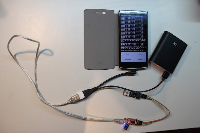
See the image below for the range of connections required. In summary:
  • The Android device needs a USB port that works in this configuration. It might or might not work on your device, and unless I have your device on my workbench I will not be able to tell you. 
  • An appropriate USB OTG Y cable that will allow you to power the BlueFly, and allow it's data to go to the Android device. I used this one
  • A power supply (that is the battery pack on the right). 
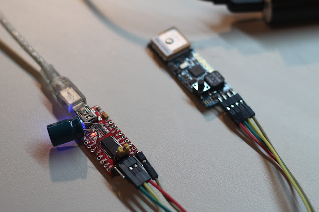
  • A USB to TTL serial converter with an FTDI chip. I used this one. Note that I modified the converter I had with a 470uF electrolytic capacitor on the 3.3V output from the chip (you can see that in the image below the image below). The FTDI chip on my converter only provides 50mA at 3.3V and when the BlueFly beeps it spikes above that, which reduces the voltage a little, which then sensing a false pressure drop, which then creates a feedback loop by beeping again as the vario thinks it is in lift. The capacitor stores just enough energy to keep the voltage steady during beeps. I did not think too hard about the value, it just happened to be one which was lying around and it worked. 
  • A BlueFlyVario_TTL_GPS.
  • Cables for to connect things as pictured. 
After you have connected everything proceed to Software Setup. 


Software Setup

First, download and install MAVCell Beta. You can read about what it was designed for at the link. At the very bottom of the description it says "Also works just for relaying serial data from the OTG port to a TCP address." This is exactly what we want. I found the app pretty easy to configure, although did have to restart a few times as I messed with different configurations. See the image below for the settings which worked for me. Note that after setting the Baud Rate to 57600, ensuring Server Mode is checked, and changing the Server/Client Port to 4353 then you need to 'Open COM Port' then 'Start COM/TCP'.

If you check 'View Feed' then you should see data coming from the BlueFly. This does not look like the pretty ASCII data, instead it is human unreadable Hex data, but don't worry, it works fine by the time it gets to XCSoar. Before proceeding with XCSoar un-check View Feed so you are not using too much CPU.


In the XCSoar devices menu select the 'TCP' client port then adjust the settings as shown below (although use the BlueFlyVario driver to start with, not the LXNAV driver). 


After that you should be able to see data coming in via TCP via the monitor. Click on 'Manage' and adjust the output mode from 'BlueFlyVario' to 'LX'. That changes the 'outputMode' seting on the BlueFly and asks it to send different data. You can view the monitor to see the LXWP0 and GPS sentences coming from the BlueFly. Now change the Driver from BlueFlyVario to LXNav and all should be well. The only reason we used the BlueFlyVario driver for a short time was to access the 'Manage' menu to change the outputMode.


All going well, your XCSoar should now have data from the BlueFlyVario_TTL_GPS over a wired connection.

Next Steps

With a little testing I found this same procedure worked to get data from the BlueFlyVario_USB_v10. Now this is kind of working I might make a future model of the BlueFly with a FTDI chip based USB connection. Please provide feedback on how this procedure works for you, and what you think you might want in the future.


Wednesday 6 April 2016

BlueFlyVario_TTL_GPSv11 released

In November 2015 I released the v11 version of the Bluetooth model. Today I am pleased to announce the release of the BlueFlyVario_TTL_GPS_v11 model. I have actually been shipping this model for a few weeks now to fulfill v10 orders, but only just got around to posting the details. Out of almost 4000 BlueFly's of various types and versions, we now have over 1500 TTL_GPS model BlueFlyVario's around the world, most of which are probably installed on Kobo eReaders running xcsoar to make pretty fully featured flight instruments.

I was not really sure that a new version of the TTL_GPS was needed. However, in the end a few factors which drove the decision included:
  • Keeping consistency in firmware and features moving forward by having a common processor type as the Bluetooth model.
  • Allowing intrepid hardware hackers the ability to add an airspeed indicator
  • Some design layout changes to help with my new production system. 
What is in the bag?

With the v11 model you get a very similar set of parts as the v10 model:
  • The main module. The PCB size is 50mm x 17 mm which is the same as the v10 and the v9. The speaker, GPS, button and header locations are in the same spot as the v10. 
  • A small piece of neoprene. This is really important. It must be placed over the pressure sensor if the sensor is exposed to any light (even light through a translucent case). The neoprene allows the air pressure through, but stops the light. Light makes the pressure sensor go crazy. It is really important to place it on the pressure sensor with the black foam side down - do not stick it to the pressure sensor - you will block the hole and it will not work! It is shown in the image below in the correct spot. 
  • Some blue PVC heat shrink cut to size. It is fine to install the module without a case if you use the heatshink.
    • Poke a small hole through one side of the heatshrink just big enough for the button.
    • Put the neoprene on the pressure sensor, and the heatshrink evenly over the module.
    • Use a heat gun, or a hairdryer on hot setting to carefully shrink the plastic around the module.
[Edit: The header and dupont connector are no longer included in the package. They have been replaced by a small piece of 4 core flat telephone cable. See this update for more information]
  • A 4x1P right angled header. Some people solder the wires directly to the module, others use the header so it is easy to remove for testing. If you use the header I suggest you trim the through-hole pins to the thickness of the PCB so they are flush with the bottom of the board. See the range of other Kobo install related blog posts so see different examples of how you might use the header. 
  • A 4x1P DuPont connector with 20 cm wires. This will fit in the header, and the wires connect to the serial port of the Kobo. You should trim the wires to be as short as possible so you minimize stray voltages.


Hardware changes

There have been a few hardware changes from the v10. Refer to the circuit diagram, pcb layout and image below. Also refer to the Bluetooth model release blog post for more information:
  • I have changed to the microprocessor to the PIC24F32KA302 and am now using the QFN package instead of SSOP. Even though it is smaller it is actually easier to solder without jumping leads, and most importantly, I have a bunch of extra IO lines to add new features. 
  • The TC1015 regulator has been upgraded to the TC2185 (3.0V for the TTL_GPS). This provides a higher max current to allow for the add-ons and has slightly better power supply noise performance. 
  • Some of the IO lines are exposed in a new way (see the image below of the bottom of the PCB): 
    • The I2C lines V+, SCL, SDA and Gnd can be used by hardware hackers for connecting the MS4525DO pressure sensor. 
    • RB10 and RB11 can used for extra buttons and LED. 
  • The solder jumpers are on the bottom of the board. In the image below SJ1 is shown closed. The jumpers have the following functions:
    • SJ1 is used to bypass the button function for turning on the module as soon as power is supplied to Vin. 
    • SJ2 is used to keep the VBACKUP power tied to Vin. I found VBACKUP was normally more pain than it was worth so I removed the extra pin. 
  • There is now a 10k pull-up resistor on the BlueFly-Tx line (which will be connected to the Kobo Rx line). This keeps the voltage high rather than floating, which in turns allows the newer Kobo Touch 2.0 and the Kobo Glo HD to proceed through the boot sequence without hanging up. 
  • I added a couple of holes to the bottom of the board to make soldering an external speaker easier, although it is still pretty tricky unless you are good at soldering.  


Firmware Changes

New features of the v11 firmware include:
  • Boot up shorts for entering the bootloader and resetting all of the hardware settings:
    • Previously to enter bootloader mode you shorted programming pads 2 and 5. Now you short SDA to ground (see the picture above). 
    • Previously to reset all the default hardware settings you shorted programming pads 2 and 4. Now you short SCL to ground. 
  • An updated ds30bootloader. This was required for the new microprocessor and to support the new boot up short mechanisms. 
  • A new hardware setting for supporting the airspeed sensor. 
Adding an airspeed sensor

An airspeed sensor shield is available separately for the Blutooth module. If you are a confident hardware hacker, and can read and understand the circuit diagrams, and want to experiment, then the connections are the same as described in the blog post about the shields.

Installation

The image below shows a simple installation on the Kobo Glo HD (without the really important neoprene and heatshrink). I hope to find some time soon to provide a more comprehensive post about the simple installation on the Glo HD. In the meantime some tips for all installs:

  • Use the neoprene, but do not use the sticky side which would block the holes in the pressure sensor.
  • Read an earlier blog post about using xci files. That is currently the easiest way to send commands to the vario (you also need to read the hardware settings manual on the support page of the website). 
  • If you get 'Waiting for GPS fix' and after 20 minutes of the vario being on, outside, and with the antenna having a clear view of the sky, the do the following debugging:

    • Check in the Devices Monitor for incoming data from the vario. 
    • Record a NMEA log and look for $GPGSV messages to assess what is going on with the satellites. 
    • Check your wires to ensure the solder quality is good, and that the wires are not routed next to other components on the Kobo circuit board which might pick up stray power. I like to keep the wire length less than 5cm. 
    • Send the command $PMTK104*37<CR><LF> to the BlueFly module a couple of times by connecting to it with a USB-Serial converter and the BlueFlyVario desktop application (<CR> and <LF> are replaced by the BlueFlyVario desktop application by the \r and \n characters respectively). This command is passed from U2, through the processor, and out from U1 to the GPS. This asks the GPS to do a full cold start and get rid of any stored Time, Position, Almanacs and Ephemeris data which might be corrupting a fix.
    • If that fails, send me an email with some images of your installation, and a NMEA log.