In April 2016 the v11 model of the BlueFly TTL_GPS was released. That model is now in use by many thousands of pilots around the world. Most pilots install the TTL_GPS model in a Kobo and run xcsoar. Today I am pleased to release a major update, the BlueFlyVario_TTL_GPS_v12.
Why a new model?
This update was driven by the reduced availability of the PA6H GPS used on the v11 (and all earlier BlueFly TTL_GPS models). Just over a year ago Sierra Wireless purchased GlobalTop, the manufacturer of the PA6H. For some time the PA6H module was available, but over the last few months all of my suppliers have run out of stock; I had to choose a new GPS.
I have selected the SierraWireless XA1110. From their website:
'AirPrime® XA1110 Multi-GNSS Module with Patch Antenna
Compact, high-precision, ultrafast TTFF Multi-GNSS positioning with integrated antenna. The XA1110 supports tracking of GPS+Glonass or GPS+Glonass+Galileo satellite system combinations to deliver superior positioning accuracy of <2.5m (with SBAS). Based on MediaTek's latest MT3333 engine, it’s the smallest integrated antenna multi-GNSS module on the market with an ultra-compact form factor of 12.5 x 12.5 x 6.8 mm.'

Firmware Changes
New features of the v12 firmware include:
See this previous post for an example of how to install the vario on the Kobo Glo HD. There are many links on that post that describe a few different ways to install the vario.
Also, see Nev's page for many examples of which serial port to use on different models, and for a great explanation of how to create a custom xci file.
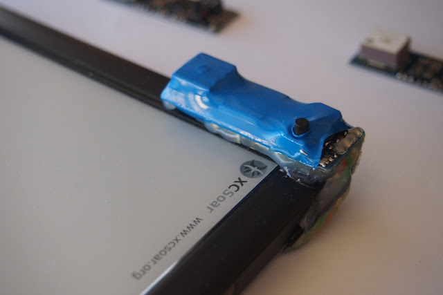
I still feel the simple install is best. The image below shows a simple installation on the Kobo Glo HD. I normally just attach the vario to the bevel which is closest to the internal serial port. I use double sided tape to hold it in place, then encase the wires and secure around the edges with hotmelt glue. In this install the xcsoar settings have been changed to landscape orientation.
Some tips which are applicable to all installs:
This update was driven by the reduced availability of the PA6H GPS used on the v11 (and all earlier BlueFly TTL_GPS models). Just over a year ago Sierra Wireless purchased GlobalTop, the manufacturer of the PA6H. For some time the PA6H module was available, but over the last few months all of my suppliers have run out of stock; I had to choose a new GPS.
I have selected the SierraWireless XA1110. From their website:
'AirPrime® XA1110 Multi-GNSS Module with Patch Antenna
Compact, high-precision, ultrafast TTFF Multi-GNSS positioning with integrated antenna. The XA1110 supports tracking of GPS+Glonass or GPS+Glonass+Galileo satellite system combinations to deliver superior positioning accuracy of <2.5m (with SBAS). Based on MediaTek's latest MT3333 engine, it’s the smallest integrated antenna multi-GNSS module on the market with an ultra-compact form factor of 12.5 x 12.5 x 6.8 mm.'
In practice, I feel that there is a significant performance improvement over the PA6H, and some better features:
The v12 is supplied with the same parts as the v11:

Hardware changes
There have been a few hardware changes from the v11.
- GPS + Glonass means quicker fixes and better tracking in many parts of the world.
- The smaller size fits better on the board, and allows for a better ground plane layout on the PCB. However, note that the patch antenna is about 1.5mm higher than the PA6H.
- For advanced users, there is good documentation on the Sierra Wireless website on sending commands to GPS module to customize its performance (in our case via the BlueFly).
- The XA1110 default baud rate is 115200 (this has resulted in some changes outlined below).
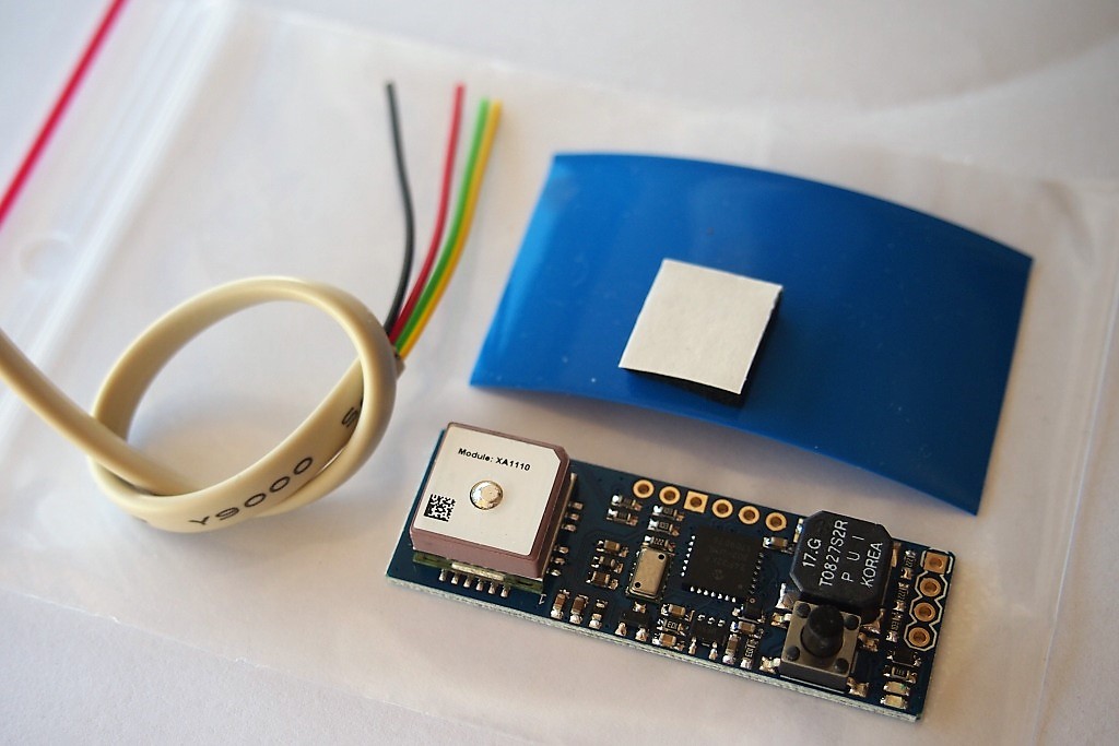
The v12 is supplied with the same parts as the v11:
- The main module. The PCB size is 50mm x 17 mm which is the same as the v11. The speaker, GPS, button and header locations are in the same spot as the v11.
- A small piece of neoprene. This is really important. It must be placed over the pressure sensor if the sensor is exposed to any light (even light through a translucent case). The neoprene allows the air pressure through, but stops the light. Light makes the pressure sensor go crazy. It is really important to place it on the pressure sensor with the black foam side down - do not stick it to the pressure sensor - you will block the hole and it will not work!
- Some blue PVC heat shrink cut to size.
- Put the neoprene on the pressure sensor, and the heatshrink evenly over the module.
- Use a heat gun, or a hairdryer on hot setting to carefully shrink the plastic around the module.
Hardware changes
There have been a few hardware changes from the v11.
- Much of the layout is identical, but the components around the GPS have been moved around for better positioning.
- The behavior of the blue LED which provides a GPS indication is now different. It is not lit to start with, and then flashes at one pulse per second when the GPS get a fix.
- There are a few pads on the back side of the board for users who want to experiment, but I recommend leaving them alone as unless you really know what you are doing:
- SJ1 is still used to bypass the button function for turning on the module as soon as power is supplied to Vin. I still do not recommend closing this for most installs. If you are considering using it then also consider using the new startDelayMS hardware setting.
- There are pads to connect a super small backup battery to the GPS VBACKUP. I feel that this is not needed for most installs, and it actually causes more problems than it solves. The pads are designed for a XH414H-IV01E battery which is currently widely available from ebay and aliexpress.
- There are pads for an external antenna header for the XA1110. Before you consider using this you should read the XA1110 documentation in detail so you know what kind of antenna to use. The pads are designed for a U.FL-R-SMT IPEX connector. I have not yet experimented with it very much.

New features of the v12 firmware include:
- There is a new hardware setting called startDelayMS.
- This adds a startup delay before data is sent to the Kobo. Some models of Kobo do not react well if data is received during the Kobo boot process. If you have closed SJ1, then you might need to adjust this setting to achieve a stable startup.
- You can adjust the duration of the delay by sending the command $BDM DELAY*, where DELAY is the delay in milliseconds.
- If startDelayMS is set to anything other than zero then you will hear two very short high pitched beeps as soon as the vario is started, then the delay happens, then the normal vario start up procedure kicks in and data starts flowing from the BlueFly.
- The default setting is 0.
- Some default values for hardware settings have changed:
- uart2BRG (BR2) = 16. The default baud rate between the BlueFly and the Kobo is now 115200, which is now the same for all of the Kobo models.
- uart1BRG (BRG) = 16. This sets the baud rate between the BlueFly processor and the onboad GPS to 115200.
- heightSeconds (BHT) = 3600. This changes the default auto power off from 600 seconds (10 minutes) to 3600 seconds (1 hour).
- toggleThreshold (BTT) = 2000. This changes the auto toggle back on feature to react to 20 m/s lift or sink, instead of 1 m/s lift of sink. Most pilots prefer to just use the button to turn the sound on and off.
- The maximum value for all hardware settings is now 65534 (0xFFFE), although I am yet to update the BFV Desktop app.
- Some pitot related code has been updated for those advanced tinkerers who are experimenting with an airspeed sensor.
See this previous post for an example of how to install the vario on the Kobo Glo HD. There are many links on that post that describe a few different ways to install the vario.
Also, see Nev's page for many examples of which serial port to use on different models, and for a great explanation of how to create a custom xci file.
I still feel the simple install is best. The image below shows a simple installation on the Kobo Glo HD. I normally just attach the vario to the bevel which is closest to the internal serial port. I use double sided tape to hold it in place, then encase the wires and secure around the edges with hotmelt glue. In this install the xcsoar settings have been changed to landscape orientation.

Some tips which are applicable to all installs:
- Use the neoprene, but do not use the sticky side which would block the holes in the pressure sensor.
- Make sure you connect the BlueFly-Tx to the Kobo-Rx, and the Kobo-Tx to the BlueFly-Rx.
- Set the baud rate in xcsoar to 115200.
- Read an earlier blog post about using xci files. That is currently the easiest way to send commands to the vario (you also need to read the hardware settings manual on the support page of the website).
- Check your wires to ensure the solder quality is good, and that the wires are not routed next to other components on the Kobo circuit board which might pick up stray power. I like to keep the wire length less than 5cm.
- If you get 'Waiting for GPS fix' shown in xcsoar, and after 10 minutes of the vario being on, outside, and with the antenna having a clear view of the sky, the do the following debugging:
- Check in the Devices Monitor for incoming data from the vario.
- Record a NMEA log and look for messages from the GPS to assess what is going on with the satellites.