Sunday, 22 December 2013

Airspeed Experiments

Over the last few months I have continued my experiments with airspeed measurements using two MS5611 pressure sensors. I built on some of the work described in this earlier post. I was initially really confident, but there are a few issues which are difficult to overcome. So now I have a new plan with a differential pressure sensor. Through this journey I learnt a lot more about how our pressure sensors work. In this blog post I will describe what I have learnt and the way ahead.

A new prototype

My main motivation in continuing with the twin MS5611 setup was to make a vario that had both super accurate static pressure changes (like the current BlueFlyVario), and could very accurately measure airspeed. I built on the design and theory outlined in this earlier post. The BlueFlyVario_Twin was designed for sailplane pilots. Bluetooth transmission of vario information from the total energy probes near the tail fin will overcome some of the accuracy issues associated with the volume of air in the tubes which normally run to the cockpit. I imagined that it would also be useful for hang glider pilots, but I am still not really confident that there is a way to mount a pitot tube for practical paraglider use.

The BlueFlyVario_Twin prototype design (see the images below) built on the basic BlueFlyVario and added some extra features:
  • The extra MS5611 pressure sensor.
  • Some more power configuration options which allow for 12V in (instead of the LiPo battery).
  • I exposed the second UART on the mirocontroller. This will allow for custom firmware to add a GPS or export the data vial TTL serial. 
  • I planned to use the more capable PIC 24F32KA301. I was running out of space on the current micro-controller. 


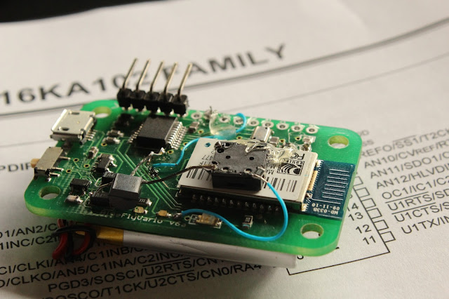
An assembled prototype is shown below. This was the test setup.


What went wrong?

In short, zero drift. Each MS5611 has a bunch of calibration coefficients. On start up these coefficients are read and then used to calculate the temperature compensated pressure. There are some remaining errors. The error from one measurement to the next is small (less than 10cm in pressure altitude terms) which means an individual sensor is perfect for use as a vario. However, the error in the absolute pressure is up to 100 times the relative pressure (about 10m in pressure altitude terms).

I thought that the error in absolute pressure could be compensated for by taking an initial measurement from each sensor at start up (when both sensors were subject to the same pressure), then applying that difference as a calibration coefficient. However, the difference drifts over time, not quickly, but over ten minutes or more it can drift far enough to mean that relative pressure measurements between the two sensors start to become inaccurate. The image below shows how the difference drifts over about two hours. The x axis is in seconds, and the y axis is the difference in pressure in pascals. To get good airspeed accuracy requires measuring differential pressure at accuracies of less than 5 pa. A drift of over 40pa would screw that up.


There is still some hope with this setup as we care more about the rate of change of differential pressure rather than the absolute differential pressure. In the data above we can see the base rate of change of differential pressure is no more than +/-0.01 pa/s. In a typical sailplane scenario on entering a thermal you might slow from 70 kts to 50 kts in 30s. The pitot pressure change would be about 300 pa (depending on air density), a differential pressure rate of about 10 Pa/s. This is a thousand fold difference from the rate of change from zero drift. This would allow for a roundabout way to calculate a total energy compensated vario measurement without the calculation of airspeed. However, I want airspeed as well so I needed another plan.

What is causing the zero drift?

I spent some time understanding how piezo resistive pressure sensors work. This document provides a wealth of great information that I will not repeat here. In summary, I suspect that each sensor is drifting based on subtle temperature dependent characteristics of each sensor. As each sensor is subject to different resistive heating the absolute pressure drifts, which is magnified for two sensors.

The way ahead

I will continue with the BlueFlyVario_Twin in a different configuration. I now plan to use a differential pressure sensor instead of the second MS5611. The first MS5611 will still be there to give accurate static vario, but the differential pressure sensor will be used for airspeed measurements. I am going to test the MEAS MS4525HRD in 0-1psi /differential configuration (http://meas-spec.com/downloads/MS4525HRD.pdf). It is designed for airspeed measurement so I suspect the zero drift will be low enough (the datasheet does not quote zero drift) . With a busy summer and some time waiting for components it will probably not be until March until I know if my new design will be good enough to progress to a prototype I will be happy for others to use. I am optimistic once again!


Sunday, 24 November 2013

Android App Updated (version 0.7b)

I just uploaded an updated version of the BlueFlyVario app to Google Play. The update will take a few hours to propagate.

New Hardware Settings

The main new feature is the addition of new hardware settings to work with the new version 7 prototype hardware. You should read this previous blog post to understand how hardware settings work. The new hardware settings for version 7 allow the BlueFlyVario to output pressure and vario data in new ways. This means it is compatible with a wider range of applications via the bluetooth SPP connection. The new settings are:

  • outputMode (default = 0) - Sets the output mode. The available output modes are:
    • 0 - The standard BlueFlyVario output mode. This sends raw pressure measurements in the form: 
      • "PRS XXXXX\n": XXXXX is the raw (unfiltered)pressure measurement in hexadecimal pascals.
    • 1 - The LK8EX1 output mode for use with LK8000. This sends pressure and vario data in the form: 
      • "$LK8EX1,pressure,altitude,vario,temperature,battery,*checksum\r\n": pressure is sent as a decimal integer number of pascals, altitude is not sent (99999 is sent instead), vario is the decimal integer vertical climb rate in cm/s, temperature is in degrees Celsius (1 decimal place), and battery is the battery voltage of the on-board battery (2 decimal places). 
    • 2 - The LXWP0 output mode for use with a range of apps: 
      • "$LXWP0,loger_stored (Y/N), IAS (kph), baroaltitude (m), vario (m/s),,,,,,heading of plane,windcourse (deg),windspeed (kph)*CS": The BlueFlyVario only has a partial implementation of this sentence. It only outputs the baroaltitude and vario (all other fields are blank). Note that baroaltidude is determined from filtered pressure using the outputQNH setting.
    • 3 - The FlyNet protocol:
      • "_PRS XXXXX\n": In this case XXXXX is output as the filtered pressure stream. The filtering parameters used are those from the other hardware settings.  
  • outputFrequency (default = 1). Sets the frequency of output sentences from the BlueFlyVario. The BlueFlyVario hardware runs on a 20ms cycle (50 cycles per second). If outputFrequency is set to 1 then the hardware will send a sentence on each cycle. If set to 2 it will send a sentance every second cycle and so on (if set to 50 is will send a sentence every 50th cycle, i.e. once per second). You might use this with the LK8EX1 output mode to send a sentence five times per second (set to 10). 
  • outputQNH (default = 101325). See outputMode = 2 above. 


You will only see the new hardware settings if you have the new version 7 prototype hardware or have upgraded the firmware on version 6 hardware. Firmware upgrade requires a microchip programmer and the hex file. If you think you can do this yourself contact me and I will send you the hex file (or you can send me your version 6 prototype and I will do it for you).

Other changes

Most other changes to the app are minor such as bug fixes associated with some European locals that use ',' as a decimal separator.

I have added rudimentary support for the new BlueFlyVario_Twin, which has two pressure sensors and can be used to calculate pitot speed and total energy compensated vertical speed. More on that in a future blog post when the new device is ready for release...

Wednesday, 20 November 2013

Audio Demonstration Video

A few people have asked me to describe how the audio on the BlueFlyVario sounds. The video below shows this in three parts. It begins with a basic audio demonstration. This is followed by a short demonstration of the sensitivity of the MS5611 and how I use neoprene to protect it from light. It concludes with a bunch of varios beeping in unison.

What collective noun should we use for a bunch of varios? Perhaps a 'bleep' of varios.


Friday, 15 November 2013

Prototype version 7 released

Prototype version 7 is ready to order! In fact, I have already shipped about 30 to those that decided to pre-order one in the last three weeks. When I released prototype version 6 almost six months ago I thought I might only make about 50. However, there are now over 200 out in the wild, and each month the number of orders continues to increase. This post will talk about the improved user and design features in the latest release.


User Features

The new BlueFlyVario prototype version 7 is pictured above. The look and feel of the design is very similar to version 6. I have kept the same case and PCB size. The LED locations have moved around a little but I do not think that most users really look at them. You will still need to complete final assembly into the prototype case yourself. See this video: http://www.blueflyvario.com/index.php/support.

Other new features include:

  • I have added support in the firmware for outputting different sentences other than the standard BlueFlyVario unfiltered pressure measurements as "PRS XXXXX" 50 times a second. The new output sentences will be enabled with new hardware settings. I will need to update the Android BlueFlyVario app then blog again to describe these new features in detail. As a teaser, the new formats are: 
    • LK8EX1 for compatibility with LK8000 devices which have bluetooth support.
    • A partial implementation of the $LXWP0 sentence (only the baroaltitude and vario fields). You might want to use this to minimize the processor power in XCSoar if you are using the audio on the BlueFlyVario instead of XCSoar. 
    • The FlyNet "_PRS XXXXX" protocol.
  • The audio frequency has been constrained so it can not be set below 130 Hz. In the last prototype the default hardware settings would mean that if you were in strong sink (below about -2.5 m/s), then the audio frequency output would be at about this level or below. The electromagnetic transducer has funky harmonics at about 125 Hz and below, and would start to sound at double or quadruple the set frequency.
  • An updated electromagnetic transducer. It is slightly louder and the one I have chosen has a footprint which is cross compatible with a range of other transducers, which means it is more likely I will be able to continue to source it. I now melt a small hole in the heat shrink so the sound comes out better.
  • I have added a solder jumper near the micro-USB port (which is open by default). If you wanted to remove the battery and power the device directly from the micro-USB port (for advanced users), then you would close this jumper. Essentially, it bypasses all of the charge circuitry. Beware: closing this jumper with the battery connected and then connecting power would destroy the battery (dangerously). 

Design Features

One of my main motivations for prototype version 7 was to design it so it was easier to assemble and test. It took around 30 minutes to assemble and test a version 6 prototype by hand. I have now got that down to 25 minutes for version 7. That might not sound like much, but when I am making them in batches of ten I save around an hour. These efficiency improvements include:

  • An updated PCB layout to make components easier to place by hand. This include aligning 0603 components in the same direction.
  • I have added more copper around the switch pads. This should make the switch more secure. 
  • The battery leads are now connected via 0.1" spaced through hole components. This makes the battery leads neater. Advanced users might also choose to remove the battery and power directly via a two pin header soldered here instead.
  • I got a commercial solder stencil with my last PCB order from http://smart-prototyping.com/. This is easier to use than my previous approach of using a DIY stencil etched from a soda can.  
The schematic and PCB layout are shown below. The gerbers or microcontroller code are available for personal use on request, please email me. 


Monday, 11 November 2013

BlueFlyVario found

This is a cool story. It is about the BlueFlyVario, but it shows that people are awesome, and that random events can be great.

Stephan was one of the first people who supported the BlueFlyVario vario project by purchasing a version 6 prototype. It was one of the first ten which means he had one with a green pcb. About a month ago he ordered another via the website. I figured he really liked it and was purchasing one for a friend. After I shipped it I forgot to ask him more about it as I got consumed in preparing version 7 (another blog post about that soon).

In the middle of last week I got an email via the website from Balazas in Hungry:
I found a Blue Fly Vario V6 device in Austria near a paragliding area in the bush last Friday while I was there for rock climbing. It was wet, and one of the plastic case is broken, but it works as I tried it. If you can help, I would send back to the owner, probably someone lost it.
It was awesome for Balazas to get in contact with me. In a later email he mentioned that he was motivated by a desire for those that do sports in the mountains to help each other as our sports can be dangerous sometimes. There was more awesomeness to come from him.

I have kept a reasonable record of who I have sent BlueFlyVario's to. I record the last four digits of the MAC address which forms part of the bluetooth name. So I asked Balazas and after his prompt response quickly worked out the vario was the first one I shipped to Stephan back in May. When he found out:
This is amazing, I lost this variometer approx 100m above ground and heard it crashing into the woods. I would not have given a penny that it is still working. I lost it about two weeks ago, so it must have been laying there in the heavy rains of last weeks, unbelievable!
I put these guys in touch with each other and Balazas quickly sent the vario back to Stephan:
A big thank you guys for finding out and sending it back to me. This is really great and a little sensation for me! First of all that someone found it second that it survived the fall from over 100 meters with very little damage and third that it found the way back home via Australia to Austria... 

You can see above the perspex protocase got cracked in the fall. A new one is on the way to Stephan right now. 

I don't recommend dropping your vario from 100m and leaving it for a few weeks in the rain. Even so, it is great to see that even with this punishment the vario still works.  In fact Balazas said when he first picked it up in the forest he turned out on and it beeped, then he paired it. Some people are awesome.

Monday, 14 October 2013

Working with other apps

The BlueFlyVairo prototype hardware is now compatible with at least three apps that I know of (other than my own BlueFlyVario Android app). XCSoar and XCTrack have been able to read the pressure stream from the BlueFlyVario for months now. Variometer - Sky Land Tracker is new. In this post I offer a few tips to get your device working with them. I don't control the ongoing development of these apps and can not provide support or endorsement. The purpose of this post is to let BlueFlyVario uses know of app choices they have.

XCSoar

XCSoar was the first app that the BlueFlyVario was compatible with. It is perhaps the most popular open source glide computer available. Here are a few tips to getting it working:

  • Use the following procedure:
    • Pair with the BlueFlyVario device in your Android device bluetooth settings (not from in the BlueFlyVario app). 
    • Turn off the vario and restart your device again (this might not be needed, but it can't hurt).
    • Install XCSoar from the Play Store
    • Ensure Bluetooth is turned on your Android device and open XCSoar. 
    • Ensure the BlueFlyVario is turned on (the next step must be done in 180 seconds or the blue flashing light will go off and you will need to restart the BlueFlyVario - you can alter this time in the hardware settings). 
    • Open XCSoar (click Fly) and go to the devices menu (Config|Config 2/3|Devices). 
    • Select device A: and click Edit. Select the BlueFlyVario device you paired with (It will be BlueFlyVario-XXXX, where XXXX are the last four digits of your mac address). Change the Driver to 'BlueFly Vario'. Keep K6Bt Off and Ignore checksum Off (I have not played with these settings).  
    • Select device B: and Edit it to Built-in GPS & Sensors. This is what Device A was before you changed it in the last step. The order of devices is important. If you did not do this then XCSoar would connect with an internal barometer (if present) instead of the BlueFlyVario. 
  • It should now be working. If not, then continue as follows:
    • Exit XCSoar and restart your Android device. 
    • Restart the BlueFlyVario.
    • Open XCSoar. 
    • Go back to the devices menu and see if it is connected. Also, does the blue light on the BlueFlyVario change from flashing to solid. If it is connected (solid blue light) but the data does not seem to be registering baro or vario you might also want to look at the Monitor from within XCSoar to see what is being streamed. 
  • Ali got this far and still could not get it working on a particular model of tablet (even though the BlueFlyVario app worked well). He managed to get it working by installing BluetoothBridge from the Play store. The bridge connects to the BlueFlyVario, then in XCSoar he connects to the bridge using TCP/IP. A novel solution to what I suspect is some kind of incompatibility between XCSoar and the bluetooth system on his device. 
XCTrack

XCTrack is more focused towards paragliding competitions. You can get it from Play here. To get it working with the BlueFlyVario you will then need to upgrade to the developmental version from within the app using Menu|Preferences|Testing and Debug|Update XCTrack. Once you have the new version installed change the 'Sensors' preference 'Use external bluetooth'. 

Variometer - Sky Land Tracker

This app is from the Korean developer SuengHo. Get it from the Play store here. There are many features I have not tested. To get it working with the BlueFlyVario click on the bluetooth icon on the main screen and follow the instructions in the app. 

If you know of other apps the BlueFlyVario is compatible let me know and I will update this blog post. 


Friday, 30 August 2013

Where are BlueFlyVarios?

After the last post a few people asked me where all the BlueFlyVarios have gone. I did a little analysis that I feel is worthwhile sharing. The graph below shows which countries the first 142 units of prototype version 0.6b have been sent to.  It is not entirely accurate as there are a few of them which I have sent to someone to pass on to others. Also it does not capture the 40 or so units of earlier prototypes. About 20 of the most recently orders ones would still be in the post. Still, it is interesting.

It is unsurprising that over a third of them have gone to Australians. A lot of these have gone to friends (thanks guys!) and friends of friends. The one to Antarctica should probably also be counted as an Australian as he is down there for work. It would be cool to see a picture of it in use over the ice. If you group Australia with NZ, US, CAN and UK then you can see around 60% of the various have gone to countries that use English as the primary language. I guess that is probably a result of how the word gets around and that my blog posts, facebook page and app are all only published in English.

European countries represent about 40% of the total. This was bumped up recently with half a dozen to a German pilot. In recent weeks I have seen increase interest from continental Europe.

It is nice to see a pair going to Israel and Iran. I do not really want to make comments on international politics, but I do like the fact that a love of paragliding is shared by many nations.

Ten going to Reunion was a bit of a surprise. I did not really know much about that French island off the coast of Africa prior to the order. It is now on my list of places I must visit for a flying holiday.

And last, thanks to my mate Jim who is doing it tough in the Philippines for a few years.


Monday, 19 August 2013

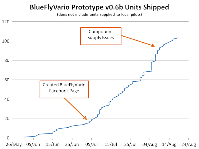
More than 100 BlueFlyVarios shipped in 10 weeks

The Last 11 Weeks

The latest prototype with on-board audio has been hugely popular, much more so than I expected. I thought there would be demand for about five units a week, but over the last month it has been more like fifteen. I have been a little overwhelmed with the interest and at times have had a few issues with component supply. Many components have a lead time of three weeks or more, and I failed to order enough of them. I think I have sorted out supply for at least the next two months unless demand increases again.

The graph below shows how the project has grown by plotting web based orders since the prototype was released on 31 May. In addition to the 100 or so units graphed below I have supplied about 20 to local pilots and non web based orders. There was a significant increase in demand just after I created the Facebook page to help spread the word, and there has been a small slowdown while I have had some component supply issues. These are now fixed and I should be ready to fulfill interest over the next few months.


Production Streamlining

I am still assembling each vario by hand. I have to say that assembling, programming, debugging, testing, packing and shipping 120 mini varios at home is not a task to be embarked on without due consideration. I have considered various options for getting someone else to do assembly and shipping. The PCB assembly part is the most obvious, but it only represents about 30% of the time to make each vario and I think outsourcing it would be more hassle than it is worth, and more expensive. I have become much more efficient at the overall process and now it takes me about half as much time for each vario as it did when I started.

I am lucky that this year I have little work in the evenings or on the weekends and have time to continue to pursue this hobby. Also, for the last eight months I have not been able to fly as I continue to recover from being broken in an accident in December last year. I should be able to get back in the air in the coming weeks and am looking forward to actually testing one of the varios myself. This will mean less time to make and develop varios if the weather cooperates, but thankfully for the project (and unfortunately for my flying prospects) the weather often offers non-flying days.

Further Development

The current version 0.6b prototype is proving stable and I intend to continue producing it for at least the next few months. Only one person has reported a error with the hardware (the switch broke) from over 100 varios in use. I have a few ideas for the next hardware version. Most of these are about making them easier to assemble. I have been very focused on hardware production and development, perhaps when I get back in the air I will focus more on making the app better.

Tuesday, 30 July 2013

Translucent Blue Cases

If you have been following the blog for a while you will know that I have been shipping the BlueFlyVario with the DP5031 prototype cases from SeeedStudio since prototype version 5. It is a great case that very adequately does the job of protecting the components on the board from knocks. Since prototype version 6 the PCB also has clear pvc heatshrink on it to help keep the battery and neoprene in place, and protect the components from dust and sticky fingers. Together the heatshink and prototype case make the device look a little polished, but it still retains the prototype look and feel.

I figured I was ordering quite a few of these cases from Seeed so approached them about getting a large custom order. With the help of Dangerous Prototypes I was able to organise for the cases to be made from translucent blue acrylic. After a few minor challenges the cases arrived earlier this week and I have already shipped a bunch with the current prototype version 6 to fulfill orders from the last week and a half.

A nice thing about the way this custom order was shipped to me from Seeed is that each prototype case came in a robust bag. When combined with a BlueFlyVario this is how it looks when I ship the components.


Not everyone is super comfortable with the prototype case. In a blog post coming up soon I will outline what others have done to design an enclosed case which can be 3D printed. 

Friday, 19 July 2013

App updated to improve performance

A rainy day gave me the opportunity to improve a few things in the BlueFlyVario app. A new version (0.61b) has been uploaded to Google Play and should push out in the next day.

Performance Improvements
  • A more efficient way to read the incoming bluetooth stream has been implemented.
  • Some code has been added to throttle the frame rate. Previously the app just tried to redraw itself as quickly as possible, and as a consequence sucked up all available cpu cycles. The frame rate is now limited to 20 fps, although you can change this through Menu|Settings|Layout and Display|FPS. If you have a slow old device you might like to slow it to 10 fps or even 5 fps. If you set it too high it will just go as quickly as possible.
  • Some memory optimizations and tuning to reduce the need for garbage collection and improve execution speed.

Stability Improvements
  • Some new code has been added to change the way that Bluetooth connections are made. If you are having problems with a stable Bluetooth connection, or being able to reliably connect, try the following:
    • Start the BlueFlyVario app. Go to the app's Menu|Settings|Bluetooth area. Ensure the normal connection method is set and ensure connect on start is not checked. 
    • Exit the app (fully, by either restarting your phone or force stopping the app)
    • Unpair the BlueFlyVario from within the Settings area of your phone, then restart your phone. At this point you should have no BlueFlyVario record in the bluetooth connections, and when you start the app it should not try to make a connection. 
    • Next, turn on the BlueFlyVario hardware and pair it with the phone from the phone's Settings area. Note that you will not need a pin on newer Android devices.
    • Now, start the BlueFlyVario app and use the Menu|Connect Device to connect. It should connect to the hardware via the 'normal' method and using the pair record from the phones Settings area. 
    • If that does not work (it might not on android 2.3.x devices), change to the 'reflection' connect method.
  • Some bug fixes to avoid very irregular application crashes. 
The best news from all of this is that the performance improvements should increase the phone's battery life while the app is running, perhaps by as much as 30% due to avoiding wasted cpu cycles. 

Tuesday, 2 July 2013

Hardware Settings

I this post I am going to try to be pretty comprehensive all of the settings that control the BlueFlyVario prototype version 6 hardware. These settings are altered from the Android app using Menu|Settings|Hardware Settings. This menu item can only be accessed when the hardware is connected to the Android app. Although many of the settings are similar to those that control the audio on the Android device, they are completely independent. Both the app and the hardware work on the raw pressure stream, and none of the hardware settings alter how that raw stream is sent out. When you change a hardware setting through the app it is altered immediately and is stored in the memory on the hardware.

Edit: This post describes hardware settings in the version 6 prototype. There are some new hardware settings for the version 7 prototype. You can read about them here.

General Settings

The first few settings are pretty self explanatory:
  • useAudioWhenConnected (default = false) - If true the hardware audio will sound when the device is connected via Bluetooth. 
  • useAudioWhenDisconnected (default = true) - If true the hardware audio will sound when the device is not connected via Bluetooth. 
Next:
  • positionNoise (default 0.1) - This setting controls one of the parameters for the KalmanFilter that is built into the hardware. A higher value gives less sensitivity by smoothing out the noisy pressure measurements. Try 1.0 to see the difference.
And near the bottom:
  • secondsBluetoothWait (default 180) - This setting controls how many seconds the hardware will keep its bluetooth radio on while waiting for a connection. 
Audio Thresholds

The audio switches on and off based on the measured vertical speed. The settings liftThreshold, liftOffThreshold, sinkThreshold and sinkOffThreshold control when the sound comes on and off. The graph below describes how this works and what the defaults are. It is fine to set the on and off thresholds to the same value, but you will get funny results if the off threshold is higher than the on threshold. 


Essentially what happens as you enter lift is that the vario senses a decreasing pressure. Note that there is a slight delay between the movement and the sensed lift due to the way the filtering works. An updated value of filtered lift gets calculated from each pressure measurement, 50 times a second (or every 20 ms). The first time the lift goes above the liftThreshold a beep is scheduled for a duration controlled by the beep cadence formula (see below). That beep will last for as long as the beep cadence, then a period of silence will be scheduled, this time based on the most recently measured lift duration. Only at that time 'beeping' could end, but if the lift continues to be above liftOffThreshold, then another sequence of beep followed by silence will be played.

Beep Cadence

When beeping commences a beep is initiated for a duration based on the measured vertical speed. As soon as the beep stops a silent pause will then be initiated, again for a duration based on the measured vertical speed. The graph below shows the formula used to control the beep duration based on the measured lift. Essentially, it means the faster you are going up, the faster the beeps will occur. Note the rateMultiplier settings can make it go faster as shown below. A rateMultiplier setting of 0.5 will make it beep twice as fast. 


Audio Tone

In addition to the thresholds and cadence, the audio tone is adjusted based on the measured speed by the four settings liftFreqBase, liftFreqIncrement, sinkFreqBase and sinkFreqIncrement. The graph below shows how the frequency changes based on these settings, and also shows what the defaults are. The frequency of the sound is constantly being updated to control the tone as the filtered vario value changes. This is occurring with every measurement (every 20 ms) whether or not the audio is on. This will result in changes of pitch in beeps as they are playing based on updated filtered vario values, and on occasion the sink tone will sound at the end of a beep if the filtered vario value changed to below 0 during a beep being played.


Volume

The BlueFlyVario uses an electromagnetic transducer. You can see the datasheet here . (Edit: I am now using this one ) These devices are driven by a square wave from a microcontroller pin (using the inbuilt PWM ). Using the trick described in the graph below the volume is controlled without needing a variable resistor. Think of the transducer diaphragm being 'kicked' by a high pulse. The more gentle the 'kick' the quieter the sound. The volume setting is not linear.

Reset Hardware Defaults

If you really screw this up, and for some reason you can not fix it through the app, then it is possible to reset the hardware settings to their default values using the procedure shown below. You might have to do this if the bluetoothWaitTime gets set to less than the amount of time required to establish a connection. 

Some Notes
  • The settings I picked as defaults are not the best. Please provide feedback by commenting on this post with what settings work for you and why.
  • The trick to a well performing vario is to get a combination of 'positionNoise' and 'liftThreshold' that works best. If you have almost no filtering (i.e. a low position noise of 0.01) then the calculated vario value will be very noisy. In this circumstance the audio threshold would need to be set at 0.4m/s or higher to avoid errant beeping. These settings would be good if we wanted the vario to be ultra responsive to really jerky movements. However, for flying we bounce around a bit more gently. A position noise of 0.1 with a audio threshold of 0.2 seemed to work pretty well for me. 
  • Most people will probably want to adjust the sinkThreshold setting to less than their glider sink rate, so it is not on all the time.
  • Battery Life will be affected by what settings you choose. The largest consumers of battery life are the bluetooth radio and the electromagnetic transducer. Having both on full time would reduce battery life to less around 8 hours. Most people want the vario to beep when they are in real lift, and the sink tone to only come on when they are in significant sink (-2.0 or so). This will mean that the audio will only be sounding for less than 50% of most flights, which would give you over well over 10 hours battery life when not connected via bluetooth. I will post a more detailed description of battery consumption in a separate post.
  • This could be a chapter of a user manual...

Sunday, 30 June 2013

Air speed from two MS5611

Some time ago on this blog I promised an experimenters version of the BlueFlyVario. Earlier today I posted details of it on the blog. My first project with this version was to add an additional two MS5611 pressure sensors so I could rig up a custom airspeed sensor. It seems to be working ok, even though I have not tested it in flight. 

The setup

I got some little boards made up that use that pick up the VDD and GND on the bottom, link to the SPI MOSI, MISO and SCLK lines, and just use two additional IO pins for cable select. The headers are designed to line up with the headers on the experimenters board.


The picture below shows a spare board in the middle, and the made up one slightly lower left. Over the top of the MS5611 I put some neoprene like my standard v6. The small pcb tangs that contain the sensors are designed so that 7mm inner diameter vinyl tubing fits over the top. The header ends of these tubes are sealed with a bit of hot melt glue. I was quite amazed how well hot melt sticks to vinyl tubing. I had thought it would just peal off, but no; it's really sticky. 


The 7mm id vinyl tubing then has some 5mm id vinyl tubing to extend to the custom pitot tube. I made this up from some brass tubing from a hobby shop, with a few holes drilled in the right place and some hot melt to seal stuff up. There is actually a thin brass tube through the middle of the main one, with appropriate connectors to pitot and static sensors. Wikipedia shows a little theory of pitot-static tube design.

Determining the air speed

The micro controller code was altered to measure the pressure from each of the three sensors. It outputs PRS N1 N2 N3, where N1 to N3 is the pressure in pascals in hexidecimal of the form XXXXX. N2 and N3 are connected to the pressure sensors on the tangs. This gives us a dynamic and static pressure measurement, 50 times a second. To translate this to m/s is as simple as

Velocity (m/s) = sqrt(2 * (N2- N3) / airdensity).

I just used the standard air density in kg/m3 in my simple testing. This gives Indicated Air Speed. The conversion to True Air Speed should be easy enough given our slow speeds and some simple assumptions about atmospheric density based on pressure. Also, it will be important to put the pitot tube in really clear airflow.

I did a few calculations on the theoretical error. If we assume the error in the differential pressure is about the same as double the error in the sensors (RMS of 20 pascals), then the error in airspeed is very low (less than 1%) for speeds over 3 km/hr. In practice there are many other errors, but a quick 'blow on pitot' test seems to be able to produce reliable results given a 'constant' amount of blowing.

My next steps will involve more extensive testing and calibration. Then maybe a total energy compensated vario.


Experimenters version ready

I promised some time ago that I would produce an experimenters version of the version 6 prototype. I have recently got a batch of these boards and done some tinkering. The pads are the same as the version 6 prototype so this is easy to make using the same solder stencil. The main difference is the line of headers along the right. These headers expose various pins from the microcontroller for additional IO options. Below is a diagram of the pcb and schematic.

If you want one of these instead of a normal version 6 prototype please contact me. I will make you up a custom version and share the code.


Blue BlueFlyVarios

Blue Boards

A few weeks ago I got a big batch of blue PCB's. The first few version 6 prototypes were green, but I have been shipping blue ones for a few weeks now and will continue to do so. This is not really a huge deal. There is absolutely no difference in terms of function, but it does look just a little cooler.


Version 6 Prototype Update

The version 6 prototypes are pretty popular. I am shipping about five a week since I announced it just over a month ago. I have enough stock of all major components to continue at this rate for a few months. Although, it will be at least a few days until I get more prototype cases (I have been out of stock for a week). This is the third time I have underestimated the demand and have been caught a little short. 

I predicted that many people would just want to use the version 6 BlueFlyVario in audio mode. This is indeed the case. Some friends have just put the board in its heatshrink in the lining of their helmet. Below is a picture of a batch of the prototypes made up and ready to ship as soon as the prototype cases arrive. 


Blue Cases

Continuing my blue theme, I have ordered a batch of custom translucent blue prototype cases. These will take at least a month or so to arrive. In the mean time I will continue shipping with the transparent case.


Wednesday, 12 June 2013

Some answers

Over the last few months I have responded to many emails, forum posts and some blog comments about the BlueFlyVario. Much of this discussion has similar themes. In this post I hope to address some issues so I can point future queries towards this page. This is kind of like a FAQ.

"It would be great to see the BlueFlyVario with a wired connection to my device"

I have spent way too many hours thinking how the BlueFlyVario could connect in a wired way. There are very many options such as;

  • a 3.3V serial (UART) connection via the micro USB pin
  • add a chip like the FT232RL that provides a USB device that acts as a virtual COM port.
  • change the PIC microprocessor to one that supports USB OTG 
  • output the data using some kind of analog encoding for input via a device microphone port. 

All of these options have issues. The main problem that I have faced is that each of these solutions would be specific to a small range of devices. Choosing Bluetooth SPP means that pretty much every device with bluetooth (except iOS stuff) can be interfaced with the BlueFlyVario. Perhaps I am influenced by the fact that every device I own or have access to that I might want to use as a flight instrument can interface to via bluetooth; however, among the six android devices (four phones, two tablets) I would struggle to create one type of wired connection that would be successful with all of them. 


"I have a pressure sensor built into my Android device. I would like to use your software with it"

I have not implemented this in the BlueFlyVario Android software as it is pretty device/Android version specific. The BlueFlyVario Android software is open and you are free to modify it to meet your needs. 

Additionally, I am not aware of an Android device with a high resolution pressure sensor. Some pilots have been happy with a vario based on BMP085 based sensor (30cm resolution at less than 50Hz), which is the kind of sensor built into those phones that have one, but most pilots feel it is a step back from their current vario. If Android devices get high resolution sensors (10cm at 50Hz), and this information can be accessed from the OS, then there will be no need for the BlueFlyVario. 


"I would like to see other sensors on board the BlueFlyVario, like GPS or multiple pressure sensors "

I have focused on just a pressure sensor because it is the key thing missing to turn an Android device into a vario. 

The GPS on Android devices is good enough for 95% of pilots. My software uses it for windspeed calculations

Some pilots, particularly glider pilots, want multiple pressure sensors arranged in such a way that pitot and static pressures can be measured. This would allow for better wind speed calculations and provide the ability for total energy compensated vario measurements. 

The Experimenters Version of the BlueFlyVario will allow those with serious tinkering skill to incorporate other sensors. I will be working on releasing that over the next few months. 


"The BlueFlyVario should cost less"

I agree. The component costs for me at batch volumes of around 50 represent about half of the device cost. The remaining 50% comes from consumables used in production, apportioned overheads used in keeping my little workshop going, packing and shipping costs, and paypal fees. At this stage it would really only be possible to get the costs down if production increased to volumes of many hundreds. I am not trying to profit from this hobby.


"Can you get the BlueFlyVario to work with other software?"

Yes. It is already integrated into XCSoar. Work is underway to integrate it in XCTrack. If you are a software developer and can access a Bluetooth SPP stream then I encourage you to look at the Android BlueFlyVario app software on GitHub for some inspiration. If you need a BlueFlyVario device for testing contact me and I will help you out. 


"How does the BlueFlyVario perform compared to other varios?

Performance is a complex question. To address some of the issues that affect responsiveness, accuracy, precision and latency I will summarize what I have experienced in BlueFlyVario development. My aim has been to get the best performance possible out of the best sensor available. 

Performance starts with the sensor. I am using the MS5611 for the reasons I describe here. Essentially, there is a relationship between the number of readings possible per second, and the RMS error in each reading. The MS5611 can theoretically provide an RMS error of around 10cm (in pressure altitude terms) at a rate of 50 samples per second (at an oversampling rate of 4096). In practice, to get this good, requires very careful circuit design to filter the power supply. I have been able to get to an RMS error of 12cm at a rate of 50 samples per second. 

Next, we need a filter on the sequence of noisy pressure measurements to turn it in to a precise estimate of the rate of change of altitude. There are many approaches to this. I started with a linear regression and IIR filter. I have tested many approaches, including an AB filter, but in the end I have settled on a Kalman filter for its performance and theoretical underpinnings. I have found that the filter choice does not matter anywhere near as much as the sensor selection and power supply design. 

The time between the filtered lift rate being above the threshold and the commencement of the beep matters quite a bit. This depends on the way code is designed on the vario and supporting software. For my new hardware audio, it is less than 5ms until the beep commences. Transmission of the pressure data over bluetooth adds around 150ms. Based on feedback from other pilots it sounds like this delay does not matter much. 

The type of audio also matters, perhaps subconsciously based on what most pilots are used to. Variable frequency and cadence based on lift rate is anecdotally important. 

The most important thing from the above list is pressure sensor selection and the power filtering on the pressure sensor supply. I have managed to get the BlueFlyVario to the point where I can lift it from chest to head height and get ultra responsive beeping. I know most pilots don't need a vario that is this sensitive, but it is a kind of addictive obsession to pursue performance. 

Most pilots who have used it say the BlueFlyVario is as good as the best varios on the market. 


Friday, 31 May 2013

Purchase page back online

The cases have arrived. That means I now continue to have a small handful of the new prototype version 6 'in stock'.

I have updated the online purchase website to buy one with PayPal

http://www.alistairdickie.com/blueflyvario/index.php/buy.


Sunday, 26 May 2013

Hardware prototype version 6 ready

After a few months of messing about with the hardware design I have settled on the final design for prototype version 6. There are a few new features, the look is more polished, and the usability has been improved.


The image above shows the final assembled prototype (on the right). I plan to ship the prototypes in a package that includes the circuit board in heat shrink (as shown on the left) and the case in component form. For version six the final assembly will be left to you. This saves me time, the postage cost is less to many destinations, and it will fill in five minutes on a quiet evening. This video shows the process for final assembly and testing.

Upgrades from earlier versions

There are a lot of little tweaks. Here are the highlights:
  • Integrated Hardware Audio. I spoke about this in an earlier blog post. I pretty much did what I said in that post. When I started the BlueFlyVario journey I was initially resistant to do anything on the device except send pressure data to a phone. However, after tinkering with the hardware audio I realised it was a feature that everyone had to have. Integrated audio makes the vario much more versatile, for the addition of only about $3 of additional components. At some point I might write a blog post that describes all of the audio settings that you can adjust on the hardware via the connected app. 
  • Heatshrink. The effect of a small piece of 43mm clear PVC heatshink makes the device feel much more robust. The heatshrink protects the components and helps hold the battery in place. The device is about 11mm thick in the heatshrink. I suspect that some users will just leave the BlueFlyVario like this, and will not bother putting it in the perspex prototype case. Especially if they are going to put it under the padding in their helmet. The PCB mounting holes can be used as tie down points. 
  • Pressure Sensor cover. The pressure sensor is really sensitive to sunlight. This meant that users of earlier versions had to hide the device away in flightdecks and pockets. A small piece of 3mm neoprene allows air pressure through but blocks sunlight completely. This is very effective and even dampens wind noise a little. I left the white cover on the neoprene to make it easier to put the heat shrink over it. Beware that pressing on the neoprene does affect the pressure so you should mount the device in a spot where it is not going to be pushed in and out often. 
  • New PCB layout. The PCB layout needed to be pushed around to incorporate the audio circuitry. Also all LED's, resistors and capacitors were changed to 0603 size, and some values were altered to optimise the design. The circuit schematic and PCB layout below shows the new design. Despite R8 being listed as a 10 ohm resistor, I am actually using a 0 ohm resistor in the final design. It makes the audio louder and does not increase current consumption much. 


So now I am planning to start churning these out at cost for collaborative hardware developers. I have made a small batch and have the parts for the next batch on order. I have put the plans for prototype version 6a (the experimenters version) on hold until I see what the initial interest is like. 

Android App Updated (version 0.6b)

I have just completed a major update of the Android app. It should be in the play store in the next 24 hours. This has been prompted by the next version of the prototype hardware, which has been shipped to a few people and will be ready for general release in the coming weeks. The key updates to the Android app are:

Kalman Filtered Pressure Stream. The hardware device sends raw pressure measurements 50 times a second. I was previously getting altitude and vario information from a complex set of IIR filtering and linear regression. That has now all changed. A kalman filter is used to keep a running estimate of position (altitude) and velocity (vario). There is only one parameter to set, the position noise (there are some other paramters that are hard coded, but these will not affect users). This turns the steam of pressure data into a stream of Alt and Vario 1 data based on the position noise parameter. The Alt and Vario 2 data is further damped using IIR filters. This makes a much simpler mix of settings and is much more computationally efficient.

Audio. The audio in the Android app was updated to make it more computationally efficient and responsive. I got rid of the "sink, sink" sound and replace it with a more familiar tone. I have also changed the default lift base frequency to 1000Hz. This is much louder on most phones speakers. The new bunch of settings should be fairly self explanatory if you read the description in the menu. Just make sure the cutoff for lift is less than or equal to the threshold, and the cutoff for sink is greater than or equal to the threshold.

Hardware Settings. In the settings menu is a sub menu that allows you to set the settings on a connected hardware device. From hardware prototype version 6 you should get a dialog similar to the one shown below. Earlier hardware versions can not access this menu. The audio settings are similar to the settings in the Android app, but are completely independent. Audio on the hardware can be enabled either when the hardware is connected to an Android device, or not, or both, or neither. The secondsBluetoohWait parameter controls how long the hardware will be available for a bluetooth connection when first turned on. The rateMultipler parameter controls how fast the lift beeps beep. 0.5 is twice as fast as 1.0. The volume parameter is a rudimentary way to set the hardware audio volume. 1.000 is default, 0.100 is about half, 0.010 is pretty quiet.


I suspect that some users of the new BlueFlyVario will only ever use the Android App to affect the hardware settings on the device.

Flight Altitude. This is a new field that shows the difference between the alt at the start of the flight, and the current alt.

In addition there are many more bug fixes, and I suspect a few new bugs. Contact me if something does not seem to work as you expect.


Friday, 19 April 2013

Hardware Audio Integration

The last few weeks have been dominated by continuing recovery from my accident at the end of last year. While that has been going on I have sent out the last few version 5 prototypes, and have been tinkering with the initial version 6a prototypes to finalise the hardware and firmware design for version 6. The most important outcome of this is my new plan to add hardware audio from version 6. The good news is that the vario will beep when not connected via Bluetooth (providing you are going up). The less good news is that all of this will delay the release of version six to some time in May.

So, how will it work. Essentially, when you turn on the vario it will start in hardware audio mode. If you go up above the lift threshold it will start beeping, if you go down below the sink threshold it will sound the sink alarm. Like other advanced varios, the audio frequency changes dependent on the lift/sink rate. For example, for the lift settings, by default the audio frequency is 700 Hz at 0.0 m/s, then increases by 10 Hz for each 0.1 m/s. The cadence also decreases from 0.5s to about 0.25s as lift increases from 0.0 m/s to 3.0 m/s. When (if) the Bluetooth connection is made the hardware audio turns off and the connected device provides the audio. If no Bluetooth connection is made within about 5 minutes then the Bluetooth is turned off to save power.

Like most of what I do, I want the audio settings, and things like the Bluetooth scan period, to be configurable. I will do this by adding a few features to the Android app that sets features on the BlueFlyVario hardware audio mode.

I spent quite some time testing a range of buzzers. I started with piezo buzzers like everyone else. I 'drove' a few using the PWM (Output Compare) from the PIC. To do this I have had to alter my planned 6a layout to swap a few pins around. The main problem with piezo buzzers in my design is twofold. First, piezo buzzers are generally driven by a higher voltage than 3V in order for them to be loud. Adding a charge pump circuit is quite a big change that I am not going to make. Second, the resonant frequency is around 4000 Hz. They are not so loud at 700 Hz.

For those reasons I chose to consider electromagnetic buzzers. They have the advantage of being smaller, having good SMD options, having better frequency response in the range I am interested in, and able to be run at 3V effectively. The main disadvantage is the need for additional components including a switching transistor and a back EMF protection diode. Overall the additional component cost is less than $2. The buzzer I am probably going to use is listed here http://au.element14.com/jsp/search/productdetail.jsp?SKU=2135919. The one I have in the test bed at home appears as loud or louder than other audio only varios. See the picture below where I have hacked in a 8mm x 8 mm buzzer. I will need to tweak the PCB layout to make it all fit...


Power consumption changes a bit. I intend to ensure there is sufficient resistance in place for the buzzer so that power consumption is less than when connected via bluetooth, without negatively effecting the loudness. This should mean that battery life will still be well over 12 hours.

As part of this tinkering I have conducted a few tests of the latency associated with the transmission of data from the BlueFlyVario and time taken by Android to respond by beeping. My test setup, with a custom app and a test firmware on the vario, essentially beeped on the hardware, then sent a signal to the Android device saying beep as soon as you can. I recorded the output in Audacity to roughly measure the delay. It varied a little depending on the code order on both devices, but by far the biggest delay is the responsiveness of the audio subsystem on the Android device. I am using older Andriod code which adds over 100 ms of latency. Newer Andriod versions (4.1) and devices are targeting 10ms or less of latency. (http://createdigitalmusic.com/2012/07/android-high-performance-audio-in-4-1-and-what-it-means-plus-libpd-goodness-today/) But for the moment for most devices the total latency averages to 150ms, which is noticeable but probably not really significant for most pilots. However, it will be for some. This means that I think that some pilots will prefer the audio to be from the hardware rather than the Android device, even when connected via Bluetooth. More custom settings...

Oh, and finally, to support the hardware audio, I have implemented a Kalman filter on the PIC micro-controller  This is going to be in the Android app as well to replace the relatively clumsy linear regression + IIR filter. 

Thursday, 21 March 2013

Experimenters Version


I am toying with an experimenters version of the BlueFlyVario. I got a batch of circuit boards made, but have only populated one for my own use. The idea is to expose all of the spare micro-controller pins so daughter boards can be designed to provide additionally functionality. Additionally, the In Circuit Serial Programming (ICSP) pins have been exposed to allow easy reprogramming of the micro-controller using a PICKIT 2 or equivalent programmer. A picture of the board design is shown below. The pins are exposed in a 0.1" series of through holes to allow standard headers. It is possible to still put the board in the DP5031 case I used for prototype version 5 (and intend to use in version 6).


Up until now I have used software SPI (bit banging) for the interface between the PIC24F16KA101 and the MS5611 pressure sensor. In this experimenters version I have moved the interface to the hardware SPI pins on the micro-controller. This has meant a pretty significant change to the firmware. It also means that adding additional devices to the SPI bus becomes less of a hassle.

The exposed pins will allow additional (spare) PIC24F hardware features to be used; including an AD channel, UART, I2C, and general IO pins. I will be using the experimenters version to get the code right for prototype version 6 (which is just the same as version 5 to look at, but will be easier to make and is electronically much more similar to this experimenters version). I have lots of ideas for daughter boards and altered firmware. These are all independent ideas, I am not thinking of doing them all in the one device!:

  • Two additional pressure sensors configured in such a way that allows connection of pitot and static tubes.
  • An LCD screen display (I have pretty much got a Nokia 84 x 48 LCD screen working already on a breadboard)
  • A small ePaper display (something like this  http://www.seeedstudio.com/depot/eink-display-shield-p-1374.html?cPath=132_134; or without the arduino integration overhead http://www.aliexpress.com/store/product/E-ink-e-paper/600281_563811171.html)
  • Integrating two high resolution 1D accelerometers. These would be physically connected to each riser. The idea is to see if I can measure the 'feeling' of wing feedback we get to improve the flight instrument. 
  • Integrating an ISM RF transceiver to transmit the vario data over ranges up to a few km. 
  • Integrating a GPS receiver to get better data than what a phone spits out.
  • Integrating a speaker to develop the code for audio output.


I still expect that the standard version 6 hardware will be what most people will want. I am intending to get quite a few of them made. The experimenters version 6a will be available in much more limited quantities for those that fell they have the electronic design skills to make use of it. My aim is to release both by the end of April with firmware code and updated schematics.

Thursday, 28 February 2013

Prototype Version 0.5b

As I recover from my accident I have been doing a little work progressing the prototype hardware to the next version. This version incorporates a few user suggestions, improves the look, and is slightly easier for me to make.

A summary of key changes from version 0.4b:
  • A new case based on the Dangerous Prototypes Sick of Beige DP5031. This is slightly smaller than a tic-tac box in length and width, but it is a little thicker. The extra $1.50 compared to a box of tic-tacs is worth it, considering that final assembly is easier, it is noticeably smaller, and it looks way cooler. A few people have mentioned that they are concerned that the sides are exposed. I am not. If you are, just put the whole thing in a small ziploc bag or 40mm heatshrink. 
  • I have switched from mini USB to micro USB for the charging point. This is the same as pretty much every Android device and it should be easier for most people. The connector is a little more flimsy, but I have been generous with the amount of solder I use to keep it on. 
  • I have changed the battery type to a 35x30x6mm 600mAh LiPo. This smaller capacity is a compromise based on what was available (I could not get more of the old one) and what would fix in the new case. The battery life is now around 12 hours, which is still way more than is really needed. 
  • The new PCB layout is a little neater. All of the LED's are lined up on the side. The RN42 antenna does not hang over the edge of PCB. Apart from looking cooler, this results in the device being easier to make.
  • I have changed a few of the tantalum capacitors to ceramics. This has reduced the electrical noise by about 10%.
I have only made a small run of prototype version 0.5b. There are a few available through the order site. See the image below:


Prototype version 0.6b is in the works. It will be very similar to version 0.5b, but with a few more PCB layout tweaks to make it even easier to manufacture. I intend to release the complete design files for that version under some sort of permissive free licence (including PCB gerbers, schematic, and PIC24F code).


Saturday, 9 February 2013

XCSoar Integration

Great news! Thanks to the XCSoar dev team (particularly Tjeerd), the BlueFlyVario is now integrated with XCSoar. For the moment the integration is in the XCSoar testing app available on Google Play here https://play.google.com/store/apps/details?id=org.xcsoar.testing&hl=en. I understand that features in the testing app will migrate to the stable version over time. Because of my injury I have not flown with this yet so my comments are based on testing on the desktop.

The BlueFlyVario pressure data sent via bluetooth is used by XCSoar in a similar manner that would be used to process pressure data from an internal pressure sensor or a serially connected device. The current implementation uses a Kalman filter to smooth the data. (http://git.xcsoar.org/cgit/master/xcsoar.git/tree/src/Device/Driver/BlueFlyVario.cpp). It provides XCSoar with barometric altitude and vario data (see line 90 and 92 of the driver).

A few tips to getting it working:

  • Make sure you have paired the BlueFlyVario with your device prior to starting up XCSoar. You should only ever need to do this once (not every time you use it). 
  • Ensure that your device's bluetooth radio is turned on prior to starting XCSoar. 
  • Ensure that the BlueFlyVario is turned on prior to starting XCSoar. 
  • Click Menu|Config|Config 2/3|Devices (You can also do the same thing through Menu|Config|Config 2/3|System|Setup|Devices - this is what the screenshot below is from). Select a disabled device and click Edit (probably "B: Disabled" if the only other device you have connected is the internal GPS). Set the "Port" to the particular BlueFlyVario device (you will only see the BlueFlyVario device here if the bluetooth radio is turned on). Set the Driver to "BlueFly Vario". At this point you might need to close and restart, perhaps reboot the device, maybe use the reconnect feature. It was a bit fiddly for me the first time around. For me now, the BlueFlyVario connection to XCSoar seems pretty robust and happens automatically. 
  • You might like to switch a few of the info boxes around. The Vario Trace one is handy to get good feedback from testing. Don't forget that to get the Barometric Altitude working you need to set QNH.
  • You might like to turn on the Audio Vario gauge.
  • You might like to change the "Look" by setting the InfoBox geometry to one that includes the  word Vario in it. 

An example of what the setup should look like.
How you could configure the screen to included extra data from the BlueFlyVario.
A todo in the XCSoar code is to do something with the BlueFlyVario battery status that is sent every ten seconds. I am not sure if that will end up being used. 

This does not mean I am going to give up on developing my BlueFlyVario android app. There are many things I still want to do with my app that I could not do easily in XCSoar. Additionally, my understanding of C magic is quite poor. I will stick with developing my stuff for Android in Java.