Wednesday, 6 April 2016

BlueFlyVario_TTL_GPSv11 released

In November 2015 I released the v11 version of the Bluetooth model. Today I am pleased to announce the release of the BlueFlyVario_TTL_GPS_v11 model. I have actually been shipping this model for a few weeks now to fulfill v10 orders, but only just got around to posting the details. Out of almost 4000 BlueFly's of various types and versions, we now have over 1500 TTL_GPS model BlueFlyVario's around the world, most of which are probably installed on Kobo eReaders running xcsoar to make pretty fully featured flight instruments.

I was not really sure that a new version of the TTL_GPS was needed. However, in the end a few factors which drove the decision included:
  • Keeping consistency in firmware and features moving forward by having a common processor type as the Bluetooth model.
  • Allowing intrepid hardware hackers the ability to add an airspeed indicator
  • Some design layout changes to help with my new production system. 
What is in the bag?

With the v11 model you get a very similar set of parts as the v10 model:
  • The main module. The PCB size is 50mm x 17 mm which is the same as the v10 and the v9. The speaker, GPS, button and header locations are in the same spot as the v10. 
  • A small piece of neoprene. This is really important. It must be placed over the pressure sensor if the sensor is exposed to any light (even light through a translucent case). The neoprene allows the air pressure through, but stops the light. Light makes the pressure sensor go crazy. It is really important to place it on the pressure sensor with the black foam side down - do not stick it to the pressure sensor - you will block the hole and it will not work! It is shown in the image below in the correct spot. 
  • Some blue PVC heat shrink cut to size. It is fine to install the module without a case if you use the heatshink.
    • Poke a small hole through one side of the heatshrink just big enough for the button.
    • Put the neoprene on the pressure sensor, and the heatshrink evenly over the module.
    • Use a heat gun, or a hairdryer on hot setting to carefully shrink the plastic around the module.
[Edit: The header and dupont connector are no longer included in the package. They have been replaced by a small piece of 4 core flat telephone cable. See this update for more information]
  • A 4x1P right angled header. Some people solder the wires directly to the module, others use the header so it is easy to remove for testing. If you use the header I suggest you trim the through-hole pins to the thickness of the PCB so they are flush with the bottom of the board. See the range of other Kobo install related blog posts so see different examples of how you might use the header. 
  • A 4x1P DuPont connector with 20 cm wires. This will fit in the header, and the wires connect to the serial port of the Kobo. You should trim the wires to be as short as possible so you minimize stray voltages.


Hardware changes

There have been a few hardware changes from the v10. Refer to the circuit diagram, pcb layout and image below. Also refer to the Bluetooth model release blog post for more information:
  • I have changed to the microprocessor to the PIC24F32KA302 and am now using the QFN package instead of SSOP. Even though it is smaller it is actually easier to solder without jumping leads, and most importantly, I have a bunch of extra IO lines to add new features. 
  • The TC1015 regulator has been upgraded to the TC2185 (3.0V for the TTL_GPS). This provides a higher max current to allow for the add-ons and has slightly better power supply noise performance. 
  • Some of the IO lines are exposed in a new way (see the image below of the bottom of the PCB): 
    • The I2C lines V+, SCL, SDA and Gnd can be used by hardware hackers for connecting the MS4525DO pressure sensor. 
    • RB10 and RB11 can used for extra buttons and LED. 
  • The solder jumpers are on the bottom of the board. In the image below SJ1 is shown closed. The jumpers have the following functions:
    • SJ1 is used to bypass the button function for turning on the module as soon as power is supplied to Vin. 
    • SJ2 is used to keep the VBACKUP power tied to Vin. I found VBACKUP was normally more pain than it was worth so I removed the extra pin. 
  • There is now a 10k pull-up resistor on the BlueFly-Tx line (which will be connected to the Kobo Rx line). This keeps the voltage high rather than floating, which in turns allows the newer Kobo Touch 2.0 and the Kobo Glo HD to proceed through the boot sequence without hanging up. 
  • I added a couple of holes to the bottom of the board to make soldering an external speaker easier, although it is still pretty tricky unless you are good at soldering.  


Firmware Changes

New features of the v11 firmware include:
  • Boot up shorts for entering the bootloader and resetting all of the hardware settings:
    • Previously to enter bootloader mode you shorted programming pads 2 and 5. Now you short SDA to ground (see the picture above). 
    • Previously to reset all the default hardware settings you shorted programming pads 2 and 4. Now you short SCL to ground. 
  • An updated ds30bootloader. This was required for the new microprocessor and to support the new boot up short mechanisms. 
  • A new hardware setting for supporting the airspeed sensor. 
Adding an airspeed sensor

An airspeed sensor shield is available separately for the Blutooth module. If you are a confident hardware hacker, and can read and understand the circuit diagrams, and want to experiment, then the connections are the same as described in the blog post about the shields.

Installation

The image below shows a simple installation on the Kobo Glo HD (without the really important neoprene and heatshrink). I hope to find some time soon to provide a more comprehensive post about the simple installation on the Glo HD. In the meantime some tips for all installs:

  • Use the neoprene, but do not use the sticky side which would block the holes in the pressure sensor.
  • Read an earlier blog post about using xci files. That is currently the easiest way to send commands to the vario (you also need to read the hardware settings manual on the support page of the website). 
  • If you get 'Waiting for GPS fix' and after 20 minutes of the vario being on, outside, and with the antenna having a clear view of the sky, the do the following debugging:

    • Check in the Devices Monitor for incoming data from the vario. 
    • Record a NMEA log and look for $GPGSV messages to assess what is going on with the satellites. 
    • Check your wires to ensure the solder quality is good, and that the wires are not routed next to other components on the Kobo circuit board which might pick up stray power. I like to keep the wire length less than 5cm. 
    • Send the command $PMTK104*37<CR><LF> to the BlueFly module a couple of times by connecting to it with a USB-Serial converter and the BlueFlyVario desktop application (<CR> and <LF> are replaced by the BlueFlyVario desktop application by the \r and \n characters respectively). This command is passed from U2, through the processor, and out from U1 to the GPS. This asks the GPS to do a full cold start and get rid of any stored Time, Position, Almanacs and Ephemeris data which might be corrupting a fix.
    • If that fails, send me an email with some images of your installation, and a NMEA log. 

Saturday, 20 February 2016

iOS support

When the BlueFly_Bluetooth_v11 was released a few months ago I promised iOS support. A busy few months have stopped me from sharing how to get the latest BlueFly working with your iPhone. Rene released version 5.0 of Flyhysky a few weeks ago which means that the most popular iOS paragliding app is now compatible with the BlueFly. Last weekend Dave (one of our local pilots) visited and we were able to do some testing and grab a few screenshots. In this post I will try to help iOS/BlueFly users.

First, a little disclaimer. I do not own any iOS devices and have never written a line of objective C for iOS apps. I know how to get Bluetooth 4.0 working on the BlueFly side, which is what the v11 BlueFly provides via the RN4677 dual mode Bluetooth module. However, we rely on others for the iOS side. I have done pretty extensive user type testing with Flyskyhy with Dave's iPhone 6.

iOS Apps

To follow this tutorial you will need two apps:
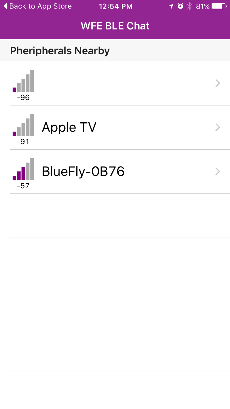
  • [Edit: The WFE BLE Chat app is no longer available - you can just skip this step.WFE BLE Chat is a free utility to communicate with Bluetooth LE devices. It is configured to work with the GATT profile supported by the RN4677. This allows us to see the raw text stream coming from the BlueFly, and also allows us to send text commands. 
  • Flyskyhy is a fully featured flight instrument app. A full description of its features can be found at flyskyhy.com

Initial Testing

To begin you might want to look at the stream of data coming from the BlueFly. You can skip this step and go straight to Flyskyhy if you want. 

Start the BlueFly. From the time it is started the BlueFly's bluetooth module is on for 180 seconds (by default). After that time, if no connection is established, it shuts down the bluetooth module until the BlueFly is restarted. So the connections described below need to be established within 180 seconds of the BlueFly being turned on. 

Open WFE BLE Chat and look for Peripherals Nearby. Select the device "BlueFly-XXXX" (where XXXX are the last four hexits of the mac address). You will then see a stream of data flowing from the device. 

At this point you do not need to do anything other than note that the raw data is streaming in. It should look like PRS XXXXX where XXXXX is the raw pressure in hexidecimal pascals. This is the default outputMode (0) of the device. Flyskyhy changes it.

Flyskyhy

Open the app and go to the apps settings menu. You need to swipe up near the bottom of the screen to bring up the settings. Select Vario|Model|BlueFlyVario then select the device. 

You will only need to do that the first time you connect. The volume slider now controls the volume on your BlueFly. In the app the Vario Status Element, the Lift Element and some of the Graph Elements are now informed by the data coming from the BlueFly. 

Advanced Settings

By using the WFE BLE Chat app you can adjust all of the advanced settings of the BlueFly. You should read the hardware settings manual to understand the serial protocol. When you open the WFE BLE Chat app after using Flyskyhy you can see that FlySkyHy changes the outputMode to 5 which makes the BlueFly send its Custom BFV Sentence. 


If you send the command $RSX* it reset the BlueFly to default settings (Flyskyhy will set it back). You might like to experiment with useAudioBuzzer ($BBZ 1* to turn it on, $BBZ 0* to turn it off) and the sinkThreholds (make sure you adjust both sinkThreshold and sinkOffThreshold). Please let me know what settings you would really like to see in FlySkyHy and we can ask Rene to add them. 

When I was messing around I noticed that it would be nice for the BlueFly to still make its on and off sounds even with its volume turned down in Flyskyhy. That is on my list of todo's for the next BlueFly firmware update (iOS users will need to find a pc...)

Sunday, 3 January 2016

Updates

With a bit of time on my hands I was able to do three updates today:

Sunday, 20 December 2015

GPS and Airspeed Shields

I was really happy to release the BlueFlyVario_Bluetooth_v11 a few weeks ago. Since then I have found some time to get the GPS and Airspeed shields ready to go. In this post I will describe how the shields work and what you need to do to integrate one to the BlueFlyVario_Bluetooth_v11. A word of warning - the shields are for experienced tinkerers who are good at soldering and want to experiment.

The Shield Concept

I have developed quite a few different BlueFly models over the past few years. It all started with a simple device that just sent pressure data via Bluetooth. In v6 I added audio, a TTL version came later, then with Kobo mods becoming popular we got the TTL_GPS model. Firmware update-able versions started with v10.

If I just kept on adding sensors and other components to the BlueFly we would end up with a device that has a lot of stuff that many people would not use. That would be a waste of time for me, and a waste of money for users. However, there were some key things I wanted to be able to offer experienced users. The micro-controller on the v11 has enough spare pins to allow extra things to be added. Instead of adding sensors on the main BlueFly board I decided to offer extra capacity with an add on shield. The 'shield' is just a small daughter-board the same size as the BlueFly board. This is sandwiched with the BlueFly and connected with headers to make a more powerful device.

The images below shows the circuit diagram and PCB layout of the shield. Note that the components which can be attached to RB10 and RB11 can either be configured as buttons or LED's depending on what is populated.


BlueFly_v11_Shield_GPS

Description: The B_v11_Shield_GPS adds a PA6H GPS on UART1 (U1) of the microcontroller. The GPS shield has a few extra components to smooth the power supply to the GPS and provide the PA6H LED output. Note that the BlueFly button protrudes through the hole in the shield. The GPS works in exactly the same way as the GPS on the TTL_GPS models of the BlueFly:

  • Any sentences coming from the GPS which begin with $ and ending with new line (\n) are echoed out on U2 by multiplexing the with the standard BlueFly output. 
  • The BlueFly does nothing with the GPS information other than pass it through. 
  • At this stage XCSoar is the only application which reads both the BlueFly output (in a few different modes) and the standard GPS sentences from the same data stream. 
Target Users: I expect that most people that want the v11 Bluefly and this add on v11 GPS shield will be wanting to connect it to a Kobo which as been modified to accept Bluetooth connections. Anyone who intends to use the BlueFly with a device that already has a GPS (like and Android or iOS devices) should not bother with this module.

Released Version: The BlueFly_v11_Shield_GPS is provided in kit form. The kit includes the items pictured below:

  • The BlueFly_v11_Shield_GPS board.
  • Some pins for connection to the BlueFlyVario_Bluetooth_v11 (these will need soldering). 


BlueFly_v11_Shield_Airspeed

Description: I have been tinkering with Airspeed for some time. It was not until I started experimenting with the MS4525DO differential pressure sensor that I found something I was happy with. This is the same sensor which is used in the PX4 airspeed sensor and is connected via I2C.

The MS4525DO upper port (the one near the top of the picture) is connected to the pitot pressure and the lower port is connected to the static pressure. The included pitot tube and clear tubing is a cheaply available RC model tube and will need modification at the nose to make it work properly as when it is machined the pitot hole gets a little closed. You will have to tinker with the physical layout of the tube to get it accurate, although note that there is no way to get accurate airspeed below about 10 to 15 km/hr.

Some additional notes (I will update the hardware settings manual at some stage):

  • The BlueFly needs a special hardware setting adjusted. To adjust usePitot send $BUP 1* to the BlueFly via the normal manner (or tick the box in the BFVDesktop application). This makes the BlueFly read this pitot sensor each cycle via I2C and adjust the sent data appropriately. This will be described fully in the manual update; but in the interim note that the LX mode sends the indicated airspeed (IAS) when usePitot is set.
  • When the BlueFly starts up with usePitot enabled it immediately begins a pitot calibration. This lights the red LED on the shield, then takes about five seconds of pitot data. The differential pressure measured is averaged and taken to be zero airspeed. 
  • You can trigger another calibration at any time by pressing the red button on the shield next to where the normal BlueFly button protrudes. It is important that the pitot tube is in no wind when the calibration is underway. 
  • If you set usePitot, but the shield is not connected, the BlueFly will send an error message. 
Target Users: I expect that most people that want the v11 Bluefly and this add on v11 Airspeed shield will be experimenting with different configurations. I am yet to be convinced that there is some logical place to put a pitot tube anywhere on a paraglider which has clean enough air; it is easier on a hangglider. At some stage I will probably design a 3D case to mount the pitot tube and vario components.


Released Version: The BlueFly_v11_Shield_Airspeed is provided in kit form. The kit includes the items pictured below:
  • The BlueFly_v11_Shield_Airspeed board. 
  • A basic pitot tube and clear tubing. 
  • Some pins for connection to the BlueFlyVario_Bluetooth_v11 (these will need soldering). 


BlueFly_v11_Shield_GPS+Airspeed

Description: This provides the capabilities of both modules in one. See the image below:


Assembly

To assemble the shield onto the BlueFly requires some skill or a friend who knows what they are doing with a soldering iron. There are many ways it could be assembled together, and in the end you will need some kind of case which houses everything. At some point I will probably design a 3d printable case but so far I have only tested it with a Frankenstein mix of tape and heatshink which will be unacceptable for most people.

Some assembly tips:

  • You will need to disassemble the BlueFly and disconnect the battery. 
  • Start by soldering the pins on to the BlueFly, short ends in the pcb from the component side, then solder from the bottom. You should use all 11 pins (4 on one side, 7 on the other). 
  • Use the 5mm standoffs from the BlueFly to position the shield above the main board. Note the button protruding through the hole at just the right height. 
  • Solder the pins to the shield from the top. 
  • Plug the battery back in (protect it from the pins with some tape), connect to the BFVDesktop application, then start testing. 
See the image below for an indication of what a shield looks like when connected to the base BlueFly.


Next Steps

There is quite a lot more to do:
  • Design a 3d printable case for use with the airspeed sensor.
  • Much more testing with the airspeed sensor. 
  • Integration of GPS and airspeed information with other apps
  • Update the hardware settings manual. 
The shields are available for purchase now. Note that I am only producing them in low volumes and will hand assemble and test each one based on the number of orders received.  


Friday, 27 November 2015

BlueFlyVario_Bluetooth_v11 released

I love releasing new models of the BlueFly. Every new model is a little milestone where I have tried to make the vario better and be more suited to a wider range of pilots. Almost a year ago to the day I released the BlueFlyVario_Bluetooth_v10. With the v11 you will get iOS support and the ability to add an air speed sensor and GPS with a separately available shield. Despite the Australian dollar exchange rate falling I have managed to keep the price the same by optimising production and selection of components. This blog post talks in detail about the new stuff following the announcement a few weeks ago. It will still take me a few weeks to catch up on orders.

What is in the bag

Back in May a new method of shipping and assembly was described. The v11 keeps this same procedure and you should watch the video before assembling the vario. The little things like trimming the screws and getting the battery lead properly placed with make the vario much neater. In the bag you will find:
  • The vario covered in heatshrink with neoprene protecting the pressure sensor. This has been bench tested. 
  • A 600 mAh battery with connector. 
  • The two sides of the prototype case, covered in protective paper you will need to remove. 
  • A pack of plastic screws and standoffs. 
  • [Edit: From 26 Apr the BlueFlyVario_Bluetooth_v11 now ships with the Sky Blue Enclosed Case]
See the image below:


Hardware Changes

Below is a close up picture of the new circuit board. 

Some of the important changes include:
  • The RN4677 bluetooth module replaces the RN42. This module is a dual mode module that supports Bluetooth Low Energy connections to iOS and also supports Bluetooth SPP connections on Android devices and on Windows. This is a new module and I had a little trouble with it initially but have managed to get it working reliably with over two months of testing. The benefits of the new module are:
    • iOS support, however it will still be a little while until some iOS apps support the vario. We are working on FlySkyHy integration. There are a few BLE testing apps which enable you to see the data stream and even send commands to the vario which have given me confidence that integration with other iOS apps will be easy. 
    • It is smaller. This means I have been able to fit more stuff on the PCB while keeping the size the same. 
    • The range is better. Earlier today a mate put the vario in his RC plane (with the air speed sensor still in development) and flew it around. The BlueFly was paired with xcsoar running on my OnePlus One and we were able to see the data streaming in from about 100m away. 
    • It is a little cheaper. 
  • I have changed to the microprocessor to the PIC24F32KA302 and am now using the QFN package instead of SSOP. Even though it is smaller it is actually easier to solder without jumping leads, and most importantly, I have a bunch of extra IO lines to add new features. 
  • The TC1015 regulator has been upgraded to the TC2185. This provides a higher max current to allow for the add-ons and has slightly better power supply noise performance. 
  • Some of the IO lines are exposed in a new way (see the image below of the bottom of the PCB):
    • U1 is used for connecting the GPS to V+, Tx, Rx and Gnd. The shield uses these for connecting a PA6H GPS. 
    • The serial Tx and Rx between the microprocessor and the RN4677 are adjacent to U1. 
    • The I2C lines V+, SCL, SDA and Gnd are used by the shield for connecting the MS4525DO pressure sensor. 
    • RA7, RB10 and RB11 are used by the shield for extra buttons and LED. 
If you are a super keen hacker and want the circuit diagram or PCB layout please contact me. 

Firmware Changes

New features of the v11 firmware include:
  • Boot up shorts for entering the bootloader and resetting all of the hardware settings:
    • Previously to enter bootloader mode you shorted programming pads 2 and 5. Now you short SDA to ground (see the picture above). 
    • Previously to reset all the default hardware settings you shorted programming pads 2 and 4. Now you short SCL to ground. 
  • An updated ds30bootloader. This was required for the new microprocessor and to support the new boot up short mechanisms. 
  • A new hardware setting for supporting the airspeed sensor. I will post more about that in a later blog. 
  • The default baud rate setting for U2 has changed. The microprocessor now communicates with the bluetooth module at 115.2k instead of 57.6k. 
The GPS/Airspeed shield

A GPS/Airspeed sensor shield will be available separately, I think from around mid December. I am still testing and want to be confident all of the features are reliable. The shield will be available as a kit with the PA6H GPS only, with the MS4525DO airspeed sensor only, or with both. The image below shows the shield next to the new vario. I will post comprehensive information when it is released.


Saturday, 7 November 2015

BlueFly_Bluetooth_v11 announced

Despite the paucity of posts, I have been feverishly working on the next version of the Bluetooth version of the BlueFly in every second of my diminishing spare time. It is almost a year since the v10 was released and it is time for an update. In this post I will preview some new features prior to the release, which I expect will occur in late November.

I am currently out-of-stock of the BlueFlyVario_Bluetooth_v10. Any orders between now and the release of the v11 will be filled with the new model. Please be patient as I get everything together.

What stays the same?
  • Pretty much every firmware feature of the v10 is available in the v11. All of the hardware settings and commands will be available in the v11. 
  • The PCB size, speaker, button location and LED colors are all the same. 
  • The prototype case and battery will not change. 
  • The price, at least for now. Some component prices have reduced, but the Australian dollar has also fallen. 
What is new?
  • The first big news is a new bluetooth module which will work with iOS. I have replaced the RN42 with Microchip's new RN4677. This is a dual mode module with both Bluetooth SPP and Bluetooth Low Energy (BLE). Most devices will continue to use Bluetooth SPP, but BLE means that iOS devices can be supported. This should mean that FlySkyHy will support the new BlueFly if I can get a prototype to Rene and he can find time to alter his code. 
  • The new PCB layout also supports an add on shield for more features. The shield, which will be available separately, can be configured with either or both of a PA6H GPS or a MS5425DO differential pressure sensor. Much of my experimentation over the last few months has been to finally get reliable airspeed measurement with easy calibration and stable performance. I will post a lot more about that when I release the shield (which will be some weeks after the new v11 is released). 
  • I have updated the micro-controller and some other components. There will be more information about these on release of the v11. 
  • Also, there will be some new firmware features. Again, more on release. 
See the image below of the prototype being tested on the workbench; the headers help with development but they are not part of the final version. 


What needs to be done before release of the BlueFlyVario_Bluetooth_v11?
  • Manufacture the first production batch of hardware - I am waiting on some components. 
  • Finalise the updated boot-loader. The new bluetooth module and micro-controller meant I have had to make many updates to to. Now I need to finish testing. 
  • Finalise the updated firmware. Again, more testing. 
  • Update the BFVDesktop pc application with new hardware settings. 
  • Update the BlueFlyVario android application. 
  • Write another blog post. 

What about the TTL_GPS and USB models?

At some stage I think I will update the TTL_GPS model from v10 to v11 so it can support the new micro-controller, but probably not for many months and I am not sure if it will support the airspeed measurement. The update to the USB model will have to wait for the v12...

Saturday, 22 August 2015

More BlueFly and XCSoar Integration

XCSoar has been a big part of the BlueFly experience for many pilots. It was about two and a half years ago when I first announced integration with XCSoar. Since that time we have seen XCSoar on the Kobo and almost 3000 BlueFly varios of different types shipped around the world. The recent release of XCSoar version 6.8 adds some features which allow for further integration with the BlueFly. I have added some experimental features to the BlueFly firmware to make this work.

[Edit: I updated the firmware the the following day to fix a bug and add one more command - see below for edits]

[Edit: These features can also be used with LK8000 - See here http://www.postfrontal.com/forum/topic.asp?TOPIC_ID=7932&whichpage=2)]

[Edit: Despite my original blog post, it now looks like version 6.8 of xcsoar does not actually include the gce event triggers in response to Airspace events]

Firmware changes

Three new commands were added in experimental firmware 10.m0810.m07. They all play some part in controlling what sounds are made by the BlueFly speaker. After upgrading the firmware don't forget to send the command $RSX* to reset to default settings.
  • The new command $BSD FFF DDD* plays a tone of frequency FFF Hz for a duration of DDD ms. 
    • FFF can be any frequency from about 150 Hz to about 8000 Hz. Outside of this range the BlueFly speaker does not work well. Note that different volume settings will alter the apparent pitch of the sound. If you send a frequency of 0 then the BlueFly will be silent for the specified duration. 
    • DDD is the duration in ms. You can send any integer up to about 32000 (i.e. 32 seconds). The duration will be rounded up to the nearest 10 ms. 
    • While the tone is playing other sounds from the BlueFly will be silenced.
    • You can send the command while another sound is playing and it will be added to a queue. 
    • For example, the command $BSD 400 100* will play a tone at 400Hz for 100 ms. 
  • The BSD command will play a sequence of sounds the one command if you use the following format: $BSD FF1 DD1 FF2 DD2 ... ... FFN DDN* 
    • The full length of the command including $ and * is limited to 82 characters, so you can fit about 7 to 10 sounds in depending on duration and frequency. 
    • Note that freq/ms pairs sent (in one command, or in a series of commands) will be put onto the queue and played in the order they were put in. The queue length is 30 10  [Edit: I updated this in 10.m08] so you can play some short tunes. 
    • For example, the command $BSD 400 100 0 150 1000 50* will play a tone of 400 Hz for 100ms, followed by silence for 150 ms, followed by a tone of 1000 Hz for 50 ms. 
  • A new command $BVU* will double the current volume (clamped to the maximum of 1000). You get a short beep each time you send the command to indicate the new volume. 
  • A new command $BVD* will halve the current volume (clamped to the minimum of 1). You get a short beep each time you send the command to indicate the new volume.
Edit: In 10.m08 I made the following additional changes:
  • Added command $BTN* in 10.m08 which simulates pressing the hardware button on the vario.
  • Fixed a bug which stopped the hardware button from silencing the vario. 
In forums I mentioned that I might implement a BAL command to play some set tunes. However, I did not want to hard code particular sequences in the firmware and I am comfortable that the BSD command will meet most needs. 

Custom XCSoar events

For some time XCSoar has had a feature to customize the interface and response to events using the custom .xci files in the XCSoarData directory. To test some of my new commands I created a bluefly.xci file. A full description of .xci files is not available; you need to dig into the XCSoar source code to understand how they work, and even then it is tricky to understand. I will try to describe the features of the .xci file format I have used. 

I have only tested basic functionality on Windows, Android and Kobo. I have not comprehensively tested in in flight and you should consider it experimental. 

First, to use the file you need to:
  • Upgrade to XCSoar 6.8 by following the directions for your device. 
  • Put the bluefly.xci file in your XCSoarData directory on your device. Depending on your device this directory will be in different locations. 
  • Restart XCSoar then Menu|Config|System|Look|Language,Input(Ensure Expert is checked)|Events then select the bluefly.xci file. Restart XCSoar again. 
The video below shows how the new firmware and bluefly.xci file works with XCSoar on the Kobo. 


The first part of the .xci file creates a new BlueFly menu item in the main menu in XCSoar:

mode=Menu
type=key
event=Mode BlueFly
label=BlueFly
location=5

The next parts of the file create the five menu items in the new BlueFly menu:

mode=BlueFly
type=key
event=SendNMEAPort1 BVU
label=Vol Up
location=1

mode=BlueFly
type=key
event=SendNMEAPort1 BVD
label=Vol Down
location=2

mode=BlueFly
type=key
event=SendNMEAPort1 RST
label=Reset
location=3

mode=BlueFly
type=key
#event=SendNMEAPort1 BSD 392 100 784 100 392 100 784 100
#event=SendNMEAPort1 BSD 262 400 0 50 262 400 0 50 392 200
event=SendNMEAPort1 BSD 392 20 0 10 392 20 0 10 392 20 0 10 392 20 0 10 392 20 0 10 
label=TestBeep
location=4

mode=BlueFly
type=key
event=Mode default
label=Cancel
location=9

The first four commands make use of the command SendNMEAPort1 event. The command will be wrapped in $ and * to make the full command sent to the BlueFly. 
  • The first two menu items adjust the volume using the new commands.
  • The next simply restarts the BlueFly. You might like to change RST to RSX to restart the BlueFly and reset all of the settings. 
  • The next menu item uses the new BSD command to send a tone sequence. I tried with XCSoar to execute two "event=SendNMEAPort1" in response to the one input, but I think that XCSoar is sending them too quickly for the BlueFly harware to parse them. That is why I ended up with the one command where a series of notes can be sent. I have used menu item to test various sounds. Note that the lines beginning with # are ignored. Note also that if your BlueFly is set up as the second device you will need to adjust the events to SendNMEAPort2. 
  • The last menu item cancels the menu and sends XCSoar back to default mode. 
The next events in the file are "Glide Computer Events", which occur when things happen in XCSoar. I am not sure if there is a comprehensive listing of gce events, but I know these two were added in version 6.8 (thanks to Peter for this great addition to XCSoar). I have not actually tested them in flight yet so I am not sure how they work with my new firmware.  [Edit: It seems we are still waiting for these events to make it into the code: http://git.xcsoar.org/cgit/master/xcsoar.git/tree/src/Input/InputQueue.hpp?h=v6.8. In the meantime see the modified bluefly.xci below]

[Edit: I am really sorry, but now I think that all of the airspace related GCE event stuff in XCSoar is not working in version 6.8 of xcsoar. The AIRSPACE_ENTER event seems to be not firing, and I dug down into the code. Although it appears on the list of events in http://git.xcsoar.org/cgit/apf/xcsoar.git/plain/src/Input/InputQueue.hpp, it looks like whatever code used to fire that event does not exist any more. The good news is that the BlueFly firmware is ready to go. So, now we just need an xcsoar developer who can commit the appropriate code.]


mode=default
type=gce
data=AIRSPACE_NEAR
event=SendNMEAPort1 BSD 392 100 784 100 392 100 784 100

mode=default
type=gce
data=AIRSPACE_INSIDE
event=SendNMEAPort1 BSD 392 20 0 10 392 20 0 10 392 20 0 10 392 20 0 10 392 20 0 10

mode=default
type=gce
data=AIRSPACE_ENTER
event=SendNMEAPort1 BSD 1000 500 800 500 600 500 400 2000 1000 500 800 500 600 500 400 2000

mode=default
type=gce
data=STARTUP_REAL

event=SendNMEAPort1 BSD 392 100 784 100 392 100 784 100

I am super interested to hear your suggestions for changing the bluefly.xci file and incorporating some more events. 

XCSoar Manage options

Another new feature in version 6.8 are some menu items to adjust a few of the hardware settings on the BlueFly from within the Devices menu. Below is a screenshot of the new Manage menu available when you have a connected device selected with the BlueFly driver. 


Only two of the hardware settings are adjustable in this release; the volume and Output Mode. Note that if you change the Output Mode to something other than BlueFlyVario you will need to also adjust the XCSoar driver. Thanks to Ben for this awesome new addition to XCSoar. 

More work

These new features of XCSoar come from our community of pilots. We are all very lucky a few guys spend some time working out how to make things happen they way they want. It is great when it all comes together.