Thursday, 2 November 2017

Airspeed Sensor Updates

Almost two years ago I blogged about an airspeed sensor shield for the BlueFly. This blog post is about a new approach to integrating an airspeed sensor with the BlueFly. It is still far from perfect, and still requires experimentation, but is a bit more accessible for those who want to tinker.

The Sensor

Instead of producing a dedicated sensor I am relying on the widely available MS4525DO based sensor which is used by the R/C community. This uses the same differential pressure sensor as the dedicated airspeed sensor I used to produce for the BlueFly. However, because of the volume of manufacturing they can be produced at a cheaper price. Search ebay, aliexpress, banggood, hobbyking, or your favorite supplier of electronics from China for 'px4 airspeed'. You should get many results. Make sure to select one of the sensors based on the digital MS4525DO (white) instead of the older analog sensor (black). You can read more about this sensor on the pixhawk website


The Enclosure

A 3d printable enclosure is designed to hold the sensor and BlueFlyVario_Bluetooth_USB_v12 (or the USB only version). It is far from a perfect design, but even on a rough 3D printer (like mine) is useful enough. You can grab the design from thingverse. Note that the lid and main part of the case are designed to be glued or held together with tape. Below is a photo of the BlueFly with airspeed sensor installed in the 3D printed case. 


Firmware Update

Before going on please update your firmware to the BlueFlyVario_12.M16 version. The firmware changes include:
  • Fixed a bug with MS5611 temperature sensor output (that is only relevant for tinkering)
  • Changed outputMode 6 (BFV Extended Sentence) to include the MS4525DO sensor temperature. The sentence is now in the following format: $BFX,pressure(Pa),vario(cm/s), MS5611temp(deg C in 2 decimal places), battery(%),pitotDiffPressure(pa), volts(V), pitotTemp(deg C in 1 decimal place)*checksum\r\n 
  • Ensured that if you send the command $BUP 1* that it always triggers an differential pressure sensor calibration sequence (which takes about 10 seconds). 
Assembly

The first step is working out what to connect to what. The sensor is connected to the I2C port of the BlueFly. You will need to ensure:
  • BlueFly-Gnd is connected to PX4Airspeed-Gnd
  • BlueFly-SDA is connected to PX4Airspeed-SDA
  • BlueFly-SCL is connected to PX4Airspeed-SCL
  • BlueFly-V+ is connected to PX4Airspeed-+5V. Note that the the BlueFly actually only provides 3.3V, but my experiments suggest that there is no degradation in performance of the MS4525DO sensor at this voltage. 


After soldering, the connections are shown below. You will need to cut and solder the wires to the length required for your enclosure. 


The image below shows the connected sensor and pitot tube mounted in the 3d printed enclosure. Note:
  • The BlueFly mainboard mounts in a similar way as in the standard sky blue case. 
  • The upper nozzle on the differential pressure sensor connects to the pitot part of the pitot tube, the lower nozzle on the static port. 
  • You should use a few dabs of hot melt glue to keep the pitot tube and px4 airpeed sensor firmly in place. 

Configuration

At the time of writing this blog post the only app which I am aware can read the indicated airspeed is xcsoar, and only when using the BlueFly in outputMode=2 (LX mode) and xcsoar configured to use the LXNAV driver. Key points:
  • You first configure the BlueFly to outputMode=2 and usePitot = true using the BFVDesktop app or by using direct serial commands. See the hardware settings manual for information about how to adjust the settings.
  • In xcsoar, set the driver to LXNAV and connect to the appropriate port (Bluetooth or over IP as appropriate for your model of BlueFly). 
  • In xcsoar, you should now see the Airspeed IAS info box provide the indicated airspeed reading. Note that this is different from the true airspeed. At low speeds (less than about 10km/hr) it will jump around quite a bit. At our paragliding and hanggliding airspeeds it should be accurate to about 1km/hr or less. 
  • Note that you can send the command $BUP 1* (this is the same as usePitot=true) to trigger a zero calibration of the differential airspeed sensor. A zero calibration will always be triggered on startup, and should be re-triggered only when the actual airspeed of the pitot is zero. 
If you really want to tinker and develop a custom app which uses the full features of the airpeed sensor then you will probably want to read the sentence from outputMode=6 ($BFX,pressure(Pa),vario(cm/s), MS5611temp(deg C in 2 decimal places), battery(%),pitotDiffPressure(pa), volts(V), pitotTemp(deg C in 1 decimal place)*checksum\r\n ) This provides the MS5611 pressure and temp, and the MS4525DO pitot differential pressure and temp. With some smart coding you should be able to calculate the true airspeed, and even develop a total energy calculation.

On the hardware side, you might want to add a push button for zero calibration. The firmware polls RB10. An internal pull up keeps it high, but if you use a push button to ground then zero calibration will be triggered. 


Todo

As always, there is more to do; manual updates, testing, more software, better physical layout for mounting in a paraglider or hangglider, etc. 

Sunday, 15 October 2017

Flying the Nova Mentor 5 in Canberra

A few months ago I starting flying a new Nova Mentor 5. It is so lovely that I decided to write a few words about it. Read on to hear about it's precision, stability, and performance.

This blog post is only loosely related to the BlueFly. One of the common queries I get from BlueFly users around the world is what wing I fly, and sometimes what the flying is like around Canberra. I will answer both of those questions in this post. 

What kind of pilot am I? In between a full time job, making and shipping well over 100 BlueFly's each month, and doing family stuff, I get time to fly. I have been flying paragliders since 1995 and am probably best characterized as a classic weekend pilot. Most of the time I stay pretty close to launch; dancing with light thermals below airspace, or making optimum use of a little ridge lift. I also fly tandem with family and friends (not commercially). 

What is Canberra flying like? Our sites around Canberra are not suited to big XC. The flying here is very technical if we want to make use of limited lift to do some little XC. We have a great club, and you can read more about flying Canberra at www.acthpa.org

Launching at Collector near Canberra - I actually ended up catching a few thermals after a sinking launch. 

Why an EN B wing? With over 20 years flying paragliders I have flown all kinds of wings. If you have been reading this blog since the beginning you may recall that I had a bad accident when flying an EN C wing. In fact, it was recovering from that accident which gave me the time to mature the BlueFly from a few prototypes to begin shipping them around the world. After that accident, I got a Nova Mentor 3 (M) and have enjoyed every flight on it.

I don't get enough spare time to travel to many far away places, or any time to fly during the week. Around Canberra we are often low to the ground and the air can be quite rowdy. A comfortable EN B wing strikes the balance between performance and stability for someone like me who might go a month without flying, and then not get many consecutive days. 

Why the Nova Mentor 5? I loved my Mentor 3 (M), but after loosing a few kg I was near the bottom of the weight range and decided to get a smaller wing. The Mentor 5 (S) had just been released so I made a quick decision to get one. I have always appreciated Nova's premium quality and support (Nova are not contributing to this by the way; I am just a happy customer). 

Shaun (in front), and me (at the back) kiting in a very light breeze
I have now flown the wing in a lot of winter thermals, and as Spring has begun in Canberra, in a few sharper thermals that throw me around. I have nothing bad to say about the Mentor 5, and love the precision, stability, and performance. 

Precision: This surprised me. Part of the reason the Mentor 5 (S) does exactly what I ask of it is because my wing loading is greater (top third of the weight range), but it is much more than that. I can hold a tighter turn and keep the wing just where I want it. When encountering turbulence I do not get thrown out of lift. I feel like the precision is at least as good as my EN C wing of four years ago.

Stability: The wing seems to stay solidly above my head, with only minor inputs required to keep it there. Even in some rough air I have only had a few little tip tucks, and they have popped out very quickly. The wing easily enters and exits big ears, and the longish brake travel seems like an inadvertent stall is very unlikely. I have not done SIV on this wing yet, but already I have more confidence than my Mentor 3. I am using speed bar much more!

Performance. Near the top of the weight range the sink rate is less than many other wings (when comparing using my 'am I at the top' test with a bunch of other pilots on a ridge). The wing is fast; at trim other pilots comment on the sound of the lines whistling though the air. On speed bar I have found I can already reach a few spots much more easily that my older wings. 

In summary, for a weekend pilot like me, the Nova Mentor 5 is a great choice. 

Well done Nova - another very pleasant wing. 


Sunday, 27 August 2017

BlueFlyVario_USB_V12 released

A busy work and family life means that I have only so much time for this hobby, and that time is almost entirely consumed by keeping up with orders for BlueFly varios; there has not been much time for development. However, today I can announce the release of the BlueFlyVario_USB_v12. This replaces the BlueFlyVario_USB_v11 and the BlueFlyVario_USB_GPS_v11.

The USB only model of the Bluefly is much less popular than the Bluetooth_USB model, (which is what you probably want if you are going to use it with a phone), or the TTL_GPS model (which is probably what you want if you are going to use it with a Kobo). Nonetheless, there are some reasons why the USB only model might be right for you:
  • If all you want are the great sounds of the BlueFly; then you can use it as a stand alone vario that beeps. 
  • If you are sure that you want to connect via USB to a PC, or to Android phone via USB OTG; then you can use it with xcsoar or another app. 
What is in the bag?

The BlueFlyVario_USB_v12 is essentially the same as the most recent revision of the BlueFlyVario_Bluetooth_USB_v12, but without the RN4678 Bluetooth module and some associated components. It has a slightly different firmware as the analog switch is no longer required to switch between the Bluetooth and USB output. See the image below for what is included:
  • The BlueFlyVario_USB_v12 mainboard. There is a small piece of neoprene covering the pressure sensor; glued at one end to hold it in place. 
  • The sky blue enclosed case. 
  • A 750 mAh singe cell Lithium Polymer battery. 
  • 4 x 5 mm M3 black nylon hex standoffs and 4 x 5 mm M3 black nylon screws.

Assembly

Follow the assembly instructions for the BlueFlyVario_Bluetooth_USB_v12.

Configuration

The BlueFly varios have many hardware settings to adjust the audio and lift/sink thresholds for beeping. See the hardware settings manual for a full description of all of the settings. Most people will just use the default settings. However, read on if you want to mess with them.

For most users the easiest way to connect will be to use the BFVDesktop application from a PC (available on the support page of the website). The v12 models of the BlueFly include a FTDI USB to serial computer. When you plug it in to your PC a virtual serial port will be installed. In the BFVDesktop application select the installed port, make sure the baud rate is 115200, then press connect. Test connection with the BlueFly by sending the $BTN* command, which simulates a button press on the actual BlueFly.

You could also configure the BlueFly from a suitable terminal application on the PC or Android by using the raw commands as described in the hardware settings manual.

Adding a GPS

I have discontinued the USB_GPS model at this stage. However, with a little basic soldering you can still add a GPS to the U1 headers. This can be done on the Bluetooth_USB model as well, but the GPS used in this example will not fit in the sky blue case with the bluetooth module and you would need to work out a way to suitably attach it to the outside.

The first step is to select a GPS which runs on 3.3v, has an included antenna, and has a TTL serial output. By default the U1 port on the BlueFly is configured to receive NMEA sentences at 9600 baud multiplex them with the normal BlueFly output, delivering the resultant data stream via the USB_Serial port at 115200. Any sentence arriving to the BlueFly at U1 which less than 82 characters long, beginning with $ and ending with *, will be gobbled up by the BlueFly and sent through.

A suitable GPS, and the one used in this example, is a widely available model used for RC flying. Search for "naze32 mini gps" on ebay, aliexpress, banggood, or where ever you get your electronic components. It is based on the ublox7 module, and I have found it to get a lock quickly and reliably. Also, it is just the right size to fit neatly in the sky blue case. Like most GPS', it defaults to a TTL output at 9600 baud which means it will work with the BlueFly without further configuration.

First, take the GPS out of its case and strip the wires. In the image below Red is 3.3v in, Black is GND, Orange is GPS-Tx (which will be connected to BlueFly-Rx), and Blue is GPS-Rx (which will be connected to BlueFly-Tx). Note that the wire colors might be different for you.


Next connect it to your BlueFly. Make sure your solder joints are clean and well made. Put a piece of tape on the BlueFly where the bluetooth module would have been to ensure there are no shorts between the underside of the GPS and the BlueFly board.


Finally, stick it to the top of the tape with more double sided tape and fold the wires away neatly. As the GPS module is just the right height you will not need the 5mm black stand offs at the GPS end of the board. It will fit neatly in the sky blue case, but make sure to be careful not to damage the button or USB connector as you put it in - do not force anything.


If you connect to the BFVDesktop app you should now see GPS sentences streaming in among the standard output from the BlueFly.

Note that it is possible for advanced users to further configure the GPS. The uBlox software to control a GPS is u-centre. It is possible to disconnect from the BFVDesktop app, and connect to u-centre. You will actually be connecting to the BlueFly at 115200 baud, even though the GPS is at 9600 baud. Some settings are available as the BlueFly sends any nmea sentence it receives from USB-Serial to the GPS as well. However, for any GPS setting feature which relies on binary communication, such as GPS firmware upgrades, then the multiplex magic of the BlueFly will not work.

Connecting to Android

Some users will want to connect the USB model of the BlueFly to their Android phone for use with xcsoar. If you have installed a GPS this might be what you could do with an Android device that does not have Bluetooth or a GPS. However, a disclaimer - I feel that that USB connectors are not designed for movement, and over time will be fragile if used on a paragliding flight deck, so I always recommend using the Bluetooth version if you have a choice. 

You will need a USB-OTG cable. The connection method is shown in the image below.


In the above image the BlueFly is connected to the UartBridge app. You can get it on Google Play here: https://play.google.com/store/apps/details?id=com.manichord.uartbridge. This app was designed to be used with the FTDI converter used on the BlueFly. It is open source and you can find it on GitHub. Thanks to Maks for the great work.

The UartBridge app will take the data coming in via USB-Serial at 115200 baud, and create TCP server on the local host to send it out on port 4353. In xcsoar you configure a device as shown below:
 

The BlueFly data (and multiplexed GPS data) will stream into xcsoar.

What about the TTL_GPS model?

At this stage I am not planning on a TTL_GPS_v12 model. The v12 Bluetooth_USB and USB models were motivated by wanting to fit in the larger 750 mAh battery, and incorporating the FTDI USB converter, neither of which applies to the TTL_GPS model. I am sure there will be mode development in the future, but I do not have anything in planning to replace the TTL_GPS at this stage.

Friday, 17 February 2017

Pressure Sensor Anatomy

At the core of over five thousand BlueFly devices is the MS5611 pressure sensor. One of the first blog posts about the BlueFly, almost six years ago, described the theoretical performance of this sensor, then about a year after that I posted about the success in testing. Back in 2011 there was not too much information about the MS5611 on the internet; only the manufacturer data sheet. Now the MS5611 is used in most of the varios which are similar to the BlueFly, and is widely used in hobby RC flying.

In this post I get technical about how the sensor works, and some of the things worth knowing about as you take care of your vario. This comes from having personally tested thousands of BlueFlys. I try to demystify how these sensors work in an accessible way, although I know it will still be pretty technical for many pilots. I focus on light sensitivity and some failure modes.

The MS5611

The image below shows the MS5611[01BA03] pressure sensor assembled on a BlueFly device. The sensor is 3 x 6 mm and is constructed of a small metal cap on top of a green circuit board. Solder pads underneath the sensor are used to connect it to the underlying BlueFly PCB, and provide power and the data interface. The BlueFly devices connect to the sensor using its SPI interface (instead of I2C) as it provides the best performance. To further improve performance the BlueFly provides power via a PI filter.

The image below shows the inside of the sensor with the metal cap removed. Inside the sensor there are two main components: a pizeoresistive absolute pressure sensing element, and a high resolution Analog to Digital Converter (ADC). It is reasonably easy to relate the functional block diagram from the datasheet to the physical layout inside.


The pizeoresistive element on the left is the MS7101. There is not too much information about it online, but you can see a few specs in this brochure. It is 1.25 x 1.25 mm, and to the naked eye looks like a grain of black sand. Infinitesimally small movements in the top of this sensor is part of where the magic happens for us. The top of the sensor is a very thin membrane of silicon with resistors etched on the surface in a particular pattern. This is like the skin of a drum on top of a hollow cavity. The silicon membrane is pushed in when you drop 10cm in altitude and about 20 trillion more molecules rush inside the metal cap of the sensor; this causes the surface resistors to change slightly. The resistors are part of a circuit which alters a voltage by a tiny bit, and the job of measuring pressure is half done. What is important for us is that it is super sensitive and repeatable as the silicon membrane flexes in and out. However, there are other things which can affect the resistance etched into the silicon other than flexing caused by pressure changes.

You can read more about piezoresistive sensing elements at the following links:
http://folk.uio.no/livfur/FYS4230/piezolecture.pdf
https://www.comsol.com/paper/download/182789/meenatchisundaram_presentation.pdf
http://pdfserv.maximintegrated.com/en/an/AN871.pdf

On the right is the ADC. Its main job is to turn the voltage from the pizeoresistive element to a digital signal. The component is more than just a standard super sensitive ADC, it also includes temperature compensation, some memory to store calibration coefficients, a digital filter, and sufficient digital circuity to allow communication the micro controller of the BlueFly. The temperature compensation removes most of the temperature induced inconstancy from the etched surface resistors in the sensing element, while the calibration coefficients allow for manufacturing inconsistency to be removed. Together these can present a super accurate digital signal. The magic of the MS5611 is that the ADC is very accurate and is designed to work at high clock speeds. This allows the BlueFly to get pressure measurements 50 times per second at 10 cm resolution, and with further processing in the BlueFly this means we can detect altitude changes very quickly.

Physical Vulnerability

The image below is taken from a slightly different angle. Here you can more easily see the vulnerability of the sensor. The holes in the cap, although tiny, are large enough for dust, grit, water, solvents, and even brush bristles, to get in. The most obvious vulnerability are the fine gold wire bonding connections. If any one of these wire connections is damaged then the sensor will not function correctly, even though it may still report a digital signal.

In addition, each of the sensor sub-components is coated in a clear sticky gel like substance; I guess for corrosion protection and perhaps some other stabilizing effect. This gel does not dissolve in water, acetone, or isopropyl alcohol, but it does seem to attract bits of dust and grit, which I think can affect either component in some circumstances.


Light Sensitivity

I spent a bit of time trying to understand the causes of light sensitivity. The video below shows the light sensitivity effect up close based on illumination from the LED's on my microscope. I think that at this range they provide the same order of magnitude light intensity as sunlight. The video pretty clearly shows that light sensitivity is due to the piezoresistive element. With a little internet research I found some theoretical descriptions of why this is the case. However, for our purposes the key is to know that protecting the sensor from light is vital to ensuring it works properly.


Sensor Protection

You need to protect your pressure sensor if you want your vario to perform well, but it also needs to be exposed to the air. The three strategies for protection are:
  • Put the whole vario in a case, although note that the translucent sky blue case used for the BlueFly does not block the light enough. 
  • Use the neoprene. I have spent some time testing different types of foam to find one which is effective at blocking the light, but permeable enough to air. The soft squishy side should be on the sensor, not the sticky side, which would block the holes. Every vario I send out has neoprene attached to the PCB in the right place, or in the kit if you are going to assemble it yourself.
  • Use a folded piece of black electrical tape, making sure that the sticky part of the tape is folded over on top of the sensor. This is a quick hack that can be done if you have lost your neoprene.
See the image below for a few examples.


Sunday, 15 January 2017

BlueFlyVario_Bluetooth_USB_v12 released

The first batch of the new BlueFlyVario_Bluetooth_USB_v12 model has been produced and all pre-orders have been shipped. I announced in the last blog post the new features of the v12 compared to the v11. In this post I will provide a more detailed description of the new design and describe the assembly procedure.

What is in the bag?

The v12 model of the BlueFly is supplied with the following components:
  • The BlueFlyVario_Bluetooth_USB_v12 mainboard. There is a small piece of neoprene covering the pressure sensor; glued at one end to hold it in place. 
  • The sky blue enclosed case. 
  • A 750 mAh singe cell Lithium Polymer battery. 
  • 4 x 5 mm M3 black nylon hex standoffs and 4 x 5 mm M3 black nylon screws. 


Assembly

Assembly is pretty simple and will take most people less than 10 minutes. I still recommend the procedure described in this previous blog post, but I have refined a few of the steps as described below:

Install Step 1 - Prepare the case 

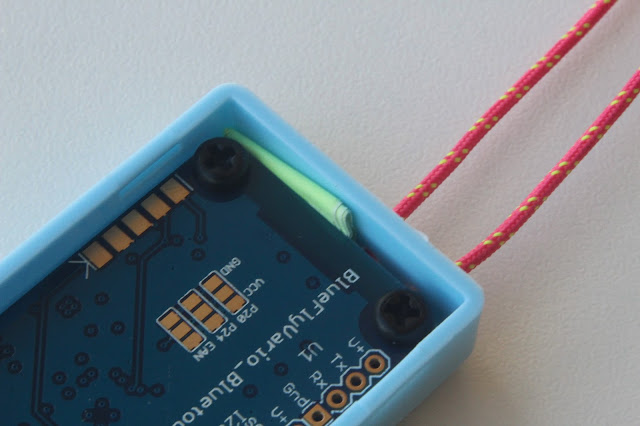
[Optional] The first part of this step is only needed if you want to put a small lanyard on the vario. Drill a couple of holes into the case at the opposite end from the USB cutout. Use a slow speed drill and only the force needed. Make sure the holes are not too close together or the small plastic in between might break if you use too much force on the lanyard. Size the holes according to whatever cord you will use. Note that on the v12 the mainboard is slightly longer than the v11 so you will need to drill the holes so that the lanyard is under where the circuit board is going to be close to the end of the case.


Next you will probably want to slightly enlarge the inside of the USB hole. I use a sharp pointed knife and just remove a small chamfer from all of the inside edges of the USB hole as shown below. This helps the micro-USB connector fit in nicely.


Install Step 2 - Screws and standoffs

Screw the hex standoffs and screws into the BlueFlyVario_Bluetooth_USB_v12 module as shown below, but be careful not over-tighten the screws; finger tight is normally enough. The hex standoffs keeps the module properly spaced from the base of the case.  You can shorten the standoffs by about 0.5mm with a sharp knife to improve the fit into the case.


Install Step 3 - Place it into the case


This is the only tricky part. Use only the force needed to place the module correctly in the case. It is possible to break either the button or the usb connector if you use too much force. Place the module in the base of the case so the button protrudes from the hole. You may find the USB connector will need a little pressure from above to push it into the hole. The edge of the PCB should be close up to the cutout end of the case and the USB connector shroud will move into the cutout (as shown below). Also see the photo from step 3 in this previous post for more information about where to gently press on the main board.  


Install Step 4 - Packing material

Put something at the other end of the PCB to keep it pressed against the USB cutout end of the case. The gap on the v12 model is about 1-2mm and I use a small piece of paper folded and placed as shown in the image below. Note the small lanyard threaded below the board.


Install Step 5 - Battery

In the v12 there is no longer any need to use double sided tape to secure the battery to the board as the lid holds it in place. Note the wires need to be neatly folded and placed as shown.


Install Step 6 - Close the case

Place the top on the case (which is now the bottom in the image shown below). I now normally run clear tape around the case to ensure the lid is held in place; this is shown as brown kapton tape below so it stands out in the image. On the v12 the battery fits snugly, and if you do not slightly shorten the standoffs in step 3 then the lid might pop off just when you don't want. 


Plug it in to recharge. The red light should come on. A single press on the button will switch it on, and a long press will turn it off. See the Hardware Settings Manual for more technical setup. 

Install Step 7 (optional)

Some pilots like to mount the vario on a flightdeck. You can use a 50 x 30mm piece of velcro (not included). To make velcro stick better heat it up with a hairdryer prior to sticking it on.


--- Technical Stuff ---

For most pilots, this is about as far as you need to read through this post. However, if you want to get technical and understand more about your BlueFly then read on. 

Firmware Changes

There are not too many firmware changes relevant for users between the last firmware from the v11 (see here for 11.M13), and the first firmware for the v12 (12.M14). In summary:
  • The UART related code has been updated to change the way data is sent with the new analog switch. It works like this:
    • If Bluetooth is not connected data is only sent and received from the Bluefly via the USB-serial chip. 
    • If Bluetooth is connected then data is sent to both the Bluetooth and USB-serial connection, but only received from the device connected via the Bluetooth connection.
  • The default hardware settings have been changed, particularly some of those associated with audio thresholds. They now reflect my preferred settings. At some stage I will update the hardware settings manual. 
  • Changing the secondsBluetooothWait hardware setting now re-enables the bluetooth module if it has been disabled. 
Hardware Design

The layout of the key components on the mainboard is described in the image below:


Some key changes from the v11:
  • The addition of the FTDI 230X USB-Serial converter now enables a data connection in the miro-USB port (instead of just charging). This makes it much easier to adjust hardware settings on a Windows PC. 
  • The addition of an analog switch controls serial data sent as described above in the firmware section. 
  • Components are spaced better and aligned more neatly. This is not just for visual appeal, but is is a 'design for manufacture' feature which makes it easier for me to assemble. 
  • The board is now about 3 mm longer, and the holes have been moved a little closer to the corners. This maximizes the space available for components and the board fits better into the sky blue case. 
All of the exposed pins are now in one row along the top side as shown in the image of the bottom of the board below:


Some key points:
  • You will not use the programming pads for the PIC or the RN4677 unless you are a super hacker and writing your own firmware from scratch. 
  • The external speaker connector is for when you want to remove the micro speaker and use a separate 16 ohm speaker. You might be able to use a 8 ohm speaker but you will need to check the levels with your test equipment and you might need to change the resistor biasing the transistor. 
  • The USB PWR jumper should be closed ONLY if you want to power the BlueFly solely from the micro USB connection, and not use the battery. DO NOT CLOSE IT WHEN USING A BATTERY - because if you did then unregulated 5V power would be provided directly to the battery which might case it to fail. 
  • Along the right:
    • The U1 V+, Tx, Rx, Gnd connectors are for connecting an external GPS as described in previous blog posts. I am considering new shields for this model. 
    • The I2C V+, SCL, SDA and GND pins are used for connecting the airspeed sensor described in previous posts. In future versions of the firmware this might also be used for other external devices. 
    • RA7 is a general purpose digital IO which is currently used for enabling and disabling an external GPS connected to U1. 
    • RB10 is a general purpose digital IO which is currently used for the calibration button on the airspeed shield. 
    • RB11 is a general purpose digital IO which is used for an indicator LED on the airspeed shield. 
    • RB4 can be a general purpose digital IO or provide an analog input. The firmware does not currently read it, but in the future I am planning to add some code to read the analog input from something like a fuel level sensor. 
    • BTN is connected to one edge of the main button. A momentary connection to VBAT will power up the vario and enable the voltage regulator. Subsequent momentary connections will then simulate a button press. 
    • VBAT is connected to the positive supply for the LiPo Battery. 
Future work

You may be able to tell that am  hopelessly addicted to trying to make the BlueFly better. Expect more stuff in the future - let me know your ideas.