Friday, 23 May 2014

BlueFlyVario_TTL_GPS_v9 Released

The BlueFlyVario_TTL_v8 has proven to be very popular to use with the Kobo. I think that most people who have ordered one want to use it with a GPS, so today I am happy to release the next version with an included GPS and upgraded firmware - the BlueFlyVario_TTL_GPS_v9.

GPS Selection

I chose the Global Top PA6H GPS for a few reasons:
  • It is pretty cheap.
  • It has good performance for low power consumption. 
  • It is small.
  • It has a sleep mode. 
  • Many people have used it (or the Adafruit Ultimate one, which is pretty much the same with slightly tweaked firmware). 
Description

The new device is shown in the image below. From a hardware perspective the only key addition was the GPS and associated LED, resistor and capacitor. 


I initially added a small switch in near the ttl serial to switch the voltage, but discovered that the Tx and Rx lines keep the device powered and sucking power. So I did not include the switch, and instead have added some firmware settings to reduce power. The device includes a neoprene cover over the pressure sensor and the device is encased in heatshrink. Also note that the TTL_GPS_v9 is shipped with the 1x4P 2.54mm header and the 4 pin dupont connector

Kobo Installation

This device is specifically targeted at installing on the Kobo. The directions in my previous blog post are all still applicable. Some users will want to solder wires directly to the device (from the back) then drill 4 x 1mm holes into the Kobo at an appropriate spot, put the wires through, then solder them to the circuit board. Others will want to solder on the 4x1P header and use the dupont connector. Post your installation pictures on the Facebook page

Firmware Updates

The v9 firmware has some important updates to hardware settings and commands:


Settings:
  • uart2BRG - $BR2 xxx* - where xxx is used for altering the baud rate of U2 (the main output). This should really only be used with extreme care, but there are a few cases where it is the only way to communicate with the GPS via the micro. 
  • uartPassthrough - $BPT x* - where x is a boolean used for passing characters received on U2 through the micro to U1. Due to different baud rates (U2 > U1) the characters are stored in a FIFO buffer of length 100. This length allows for normal NMEA commands when the baud rates are different. 
  • uart1Raw - $BUR x* - where x is a boolean used to indicate if characters received at U1 are should passed straight through to U2 or recorded line by line (i.e. $...<LF>) and then multiplexed with pressure output. This is used to allow bulk transfer of information that is sent by GPS other than standard NMEA sentences. 
  • greenLED - $BLD x* - where x is a boolean to indicate if the green LED is lighted for each lift beep.
  • outputMode - I added a new outputMode = 4, which essentially stops the pressure output. 
Commands:
  • $RST* to reset the module, essentially a hot reboot. 
  • $RSX* to reset the module and reset all of the hardware settings to factory defaults, an extended hot reboot equivalent to start up with programming pads 2 and 4 shorted. 
  • $SLP* to send the module to sleep mode. Note it also sends the PA6H GPS to sleep mode using the PMTK standby command. The micro plus pressure sensor consumes about 0.05mA in sleep mode, but the GPS still consumes about 1.5mA. To wake from sleep mode without a power cycle you just send any character to the module on U2. This will then force a hot reboot, and you are back to the power on state, including the GPS. 
I should get around to updating the hardware settings manual and BFVDesktop app for these new settings by the time shipments arrive. 

The TTL_v8 and v8(Bluetooth versions)

I will be shipping future BlueFlyVario_TTL_v8 and BlueFlyVario_v8 (Bluetooth) with the new V9 firmware from today.

However, note that the BlueFlyVario_v8 (Bluetooth) are currently on back order. I am still waiting on components (sorry). I should be able to ship in a few weeks. 

Schematics

The schematic and pcb layout for the new device is shown below. 


Friday, 25 April 2014

BlueFlyVario_TTL integration with the Kobo

Since I released the BlueFlyVario_TTL a few weeks ago many people have purchased one to integrate with the Kobo for use with XCSoar. The purpose of this post is to provide a few tips. It is by no means a complete tutorial for beginners. Integration with the Kobo requires careful soldering and software manipulation shills.

Step 1 - Get your Kobo

The Kobo mini is currently being sold for around $50. I understand they are no longer being produced and most stockists are getting rid of them at cost. Other devices such as the Kobo Touch can be used in a similar manner. At some stage these devices will be hard to find.

Step 2 - Make sure it works as a standard eReader

After purchasing the Kobo you should configure it like a normal eReader as per the instructions that came with it. This is important to do prior to installing XCSoar.

Step 3 - Back up the SD Card

The device has an SD card inside which includes the operating system and applications. Open up the Kobo and put the SD card into a reader. Create an image of it with win32DiskImager or your favourite sd card imaging software. Save the backup image somewhere where you will not loose it. Make sure to turn off the kobo prior to the next step.

Step 4 - Solder wires to the internal serial port

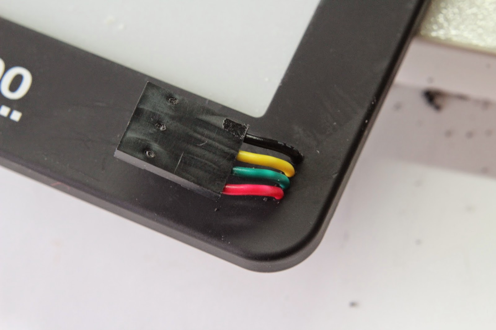
Take off the back covers and identify the serial port in the bottom left of the circuit board. The images below shows a good location for the wires and holes if you want your BlueFlyVario_TTL mounted on the front of the device. I have used a 4 port 2.54mm pitch dupont housing to plug the BlueFlyVario_TTL into. I drilled the holes from the rear and matched each size hole with the diameter of the wires. Note that the Rx from the Kobo needs to match to the Tx from the BlueFlyVario_TTL, and the Tx from the Kobo needs to match to the Rx from the BlueFlyVario TTL.


The holes were drilled from the rear. The solder residue on the serial port is from a previous installation.


The holes look pretty small from the front.

Push the wires through from the front prior to soldering.


Soldering the wires is a little tricky. I started with a dab of solder on each solder hole, tinned the trimmed wire with solder, then angled each one into the hole after reheating it with the iron. Note that the ground is much more difficult to solder as the heat is rapidly drawn away by the larger copper pour on the Kobo PCB.

Step 5 - Install XCSoar

The Kobo XCSoar image and instructions can be found here: http://www.xcsoar.org/download/.  I will not cover how to do this in great detail; there is heaps of information on the XCSoar forums and other internet resources to help you out.

Step 6 - Test the BlueFlyVario_TTL is working

After you have XCSoar working, and the Kobo is on, plug in the TTL to the front of the device. You should here it's startup beep. Next:

  • Double tap on the screen to bring up the Menu.
  • Go Config|Config 1/3|Devices
  • Ensure device A is selected and tap Edit
  • Change the following settings:
    • Port: ttymxc0
    • Baud rate: 57600
    • Driver: BlueFly Vario
    • Ignore checksum: On
  • Click ok, then Monitor to see the incoming data stream. 
Step 7 - Attach a GPS to the BlueFlyVario_TTL U1 port

Incoming GPS data (NMEA sentences) will be streamed via U1 on the BlueFlyVario_TTL and multiplexed with the BlueFlyVario output stream. XCSoar can read the combined stream from the single port. The image below shows a cheap NEO-6M module connected directly to the BlueFlyVario_TTL. The BlueFlyVario expects a 96008N1 serial input from the GPS. Read the section of the BlueFlyVario Hardware Settings Manual for more information about the second serial port. 


Step 8 - Configure the BlueFlyVario_TTL Hardware Settings

This bit was pretty tricky to work out. Thanks to Steve Nagle for his help. In fact, it was pretty much all worked out by him.

The aim is to alter the BlueFlyVario hardware settings directly from the Kobo (linux) command line without having to plug the vario into a windows PC. This is how you do it:
  • Restart the Kobo with XCSoar on it.
  • Press "Network" at bottom of screen. 
  • At top of screen press the button where it says "Wifi ON" (this turns the Wifi on - button then confusingly shows text "Wifi OFF" meaning that pressing it again will have that effect)
  • Press the button "Wifi" to select a Wifi network, connect to your network (The Kobo will display 'connected' next to network name on Wifi page).
  • Once connected press Close button on the wifi page
  • Use a pc and browser to log into your router to find out what network ip address it has allocated to your Kobo (my router is accessed by typing 192.168.1.1 into the browser address box - Google your router brand to find out what it's default internal ip address (and username / password is)
  • On the Kobo press the "Telnet server" button to start telnet on kobo
  • On your PC Telnet to the ip address you found with root as username, no password. In linux use the telnet command at the command prompt, or in windows download a program called Putty and use that. 
  • You should now have a command prompt on your PC. Your PC is now the screen and keyboard for your Kobo, which runs linux. (Type ls and hit return - you should get a directory listing).

Now communicate with the BlueFly over the serial port using commands as follows:
  • stty ospeed 57600 ispeed 57600 -F /dev/ttymxc0  'changes baud settings to match BlueFlyVario.
  • stty -F /dev/ttymxc0 raw  'makes sure the terminal program in linux sends off characters as they arrive.
If you want to see the BlueFly output do this (or skip it if you like)
  • cat /dev/ttymxc0  'test to display the output from BlueFlyVario
(here is a sample of output)
$GPGGA,025704.101,,,,,0,0,,,M,,M,,*4C
PRS 18681
PRS 18680
$GPGSA,A,1,,,,,,,,,,,,,,,*1E
PRS 18680
PRS 18681
PRS 18680

Now press ctrl C to stop that. 

Now we will adjust some settings. These are just examples. See Annex A to the the Hardware Settings Manual for a detailed technical description of the settings. 

Type the following:
  • echo '$BVL 50*'>/dev/ttymxc0  'Sets the volume on the BlueFlyVario to 50.
  • echo '$BOF 10*'>/dev/ttymxc0 'This command changes the output rate to five sentences a second (from the normal 50 (i.e. 50/10)). I think this lessens the CPU workload on the Kobo to handle so many characters over the UART. 
  • echo '$BOM 2*'>/dev/ttymxc0 'This command changes the output format to the LX protocol. Again this lessens the workload on the Kobo as vario value (rather than raw pressure value) is read from the incoming stream. You need to also change the XCSoar driver from 'BlueFly Vario' to 'LX / Colibri' if you change this setting.
  • cat /dev/ttymxc0  'Again to test the display. 
Now press ctrl C to stop that. Type exit to quit. Turn Wifi off and reboot the Kobo. 

More Pictures

Below are some more pictures from Steve's install.


Next Steps

Installing the BlueFlyVario_TTL on the Kobo with XCSoar has proven pretty popular. I am working on another version of the BlueFlyVario_TTL which includes a GPS onboard so there is no need to do that step. I am thinking the PA6H will be a good fit. The board could end up looking like this:


Note the switch so you can continue to use it as a eReader without draining power. Before I get this working I need to add a new setting in the firmware which allows configuration of the GPS when it is attached. More work to do...


Saturday, 5 April 2014

BlueFlyVario_TTL version 8 released

I have spent many months working on the BlueFlyVario_TTL. This post announces a limited release. Anyone can purchase one, but it is ‘limited’ because you will need some electronics skill to make it work the way you want. I will release another version of this in the next few months with extra components, but I am still not sure what is the best configuration.

I made a deliberate decision to produce a simpler version of the BlueFlyVario, rather than pursue the standard approach taken by many developers to make something more complex. This is a lot harder than it sounds.

I initially decided to pursue something like the TTL in an effort to produce an audio only vario module with the same awesome audio which the standard BlueFlyVario provides. Wide interest in modifying the Kobo eReader pushed me towards exposing a TTL serial interface, but with only one port available on the simple eReaders I had to multiplex GPS information using the second serial port on the micro controller. Development of this lead to the change in the BlueFlyVario version 8 which I released in the previous blog post.

Description

Compared to the standard BlueFlyVario with Bluetooth, the baseline BlueFlyVario_TTL is simply just a populated PCB which is programmed with the BlueFlyVario firmware. There is no Bluetooth module, battery or case. The key specifications are summarized in the image below:

  • 1: Second serial interface. A serial port of the PIC microcontroller (UART1) is exposed with V+, Rx, Tx and GND (3.3v). By default it is configured at 9600 Baud to accept NMEA sentences from widely available GPS modules. Sentences starting with $ and ending with /n (carriage return character) are stored then immediately multiplexed with the information being sent out the primary TTL Interface. XCSoar is smart enough to interpret the multiplexed stream via a single device.
  • 2: Pressure sensor. The MS5611 pressure sensor is a super accurate little temperature compensated module with a digital interface. The surrounding components filter the power supply. When shipped this component is covered with neoprene to avoid light sensitivity (but do not press on it when active to avoid touch sensitivity). 
  • 3: Microcontroller. The PIC24F16KA301 is running at 8MHz. This is fast enough to provide advanced Kalman filtering of the pressure measurements (which is reads from the pressure sensor at 50 times a second). At this speed the micro controller can also handle reading and sending data over the two serial ports. 
  • 4: Speaker interface. Super keen experimental users might want to integrate the audio signal into a headset. 
  • 5: Solder jumper. If you want to disable the integrated transducer clear this solder jumper.
  • 6: Status LED. This lights up with every beep. 
  • 7: TTL Interface. The primary interface (which is actually UART 2 on the microcontroller) is used to provide power to the device and send and receive data via Tx and Rx (at 57600 kps). See the hardware settings manual for detailed information about the interface.
  • 8: Programming Pads. I program the firmware using a PICKIT 3 and this pads. Short pads 2 and 4 when turning on to reset the hardware settings (see the Hardware Settings Manual). 
  • 9: Voltage Regulator.  A Microchip TC1015 LDO voltage regulator outputs 3.0V to run the micro controller and pressure sensor. It works with input power between 3.3V and 6V. Below about 3.2 V it fails to provide a stable voltage to the pressure sensor. Standard 3.3V in from other low voltage TTL devices (such as the Kobo) work well. 
  • 10: Audio. An integrated small electromagnetic transducer provides the kind of pleasant sounding vario that is normally reserved for bigger devices. 

Use

To make the TTL work you will need to do the following:

  • Provide power. I have deliberately not included a battery and switch. There are so many options and everyone has a slightly different need. You might choose to power it with a 1S LiPo, 3 x AAA alkaline batteries, power from USB, or power it from a Kobo. Whatever you choose you need to do ensure you meet the following specs.
    • Voltage: The TTL needs between 3.3V and 6V at the V+ pin on the main TTL interface end (do not provide power to the other end).
    • Current: The device consumes 10mA when not making noise, and around 50-60mA when sounding. Assuming a duty cycle of silence:noise of about 4:1 the average current consumption is about 20mA.
  • Provide a programming interface. A USB to Serial connector provides the ideal programming interface. This is used to configure the hardware settings if you want to change the defaults. You can get cheap USB to TTL serial converters on ebay, at hobby king or electronics shops like Sparkfun. I am considering including one in future releases of the TTL. 
  • Provide a data interface for external applications. If you want the vario data to be sent to an external application you can use the aforementioned USB to Serial convertor (for devices that support such a converter). Other devices (such as the Kobo) can be wired directly to the Tx and Rx pins. 


I envisage that the TTL can be used in many ways once it has been configured via the programming interface. Some examples:

  • Audio only mode. In this mode you only need to provide power and it will work. Something like a 3 x AAA case with integrated switch should meet the needs of most people. I am considering including one of these in future releases with the baseline configuration.
  • Integrated Helmet vario. The board is small enough to be integrated into a helmet. In this configuration a small RC 1s LiPo of around 600mA provides heaps of juice. A switch in series allows it to be turned on and off in flight. 
  • Integration via USB to a Linux device. Some users in sailplanes might want to integrate the vario directly into a Linux device via a USB to serial interface. I understand a few people are going to try to encase the vario and connect it to the TE probe. I am keen to get feedback. 
  • Integration with a Kobo. The picture below shows how I have integrated it with the Kobo on my workbench. In this configuration the Kobo is providing power to both the BlueFlyVario_TTL and the attached GPS module. This type of GPS module, based on the NEO-6M chip, is widely available and the default settings should work for most users. 


Schematics

The images below show the schematic and PCB layout for the BlueFlyVario_TTL version 8 prototype.


Monday, 31 March 2014

BlueFlyVario version 8 released

I am super happy to release the BlueFlyVario version 8 prototype together with the BlueFlyVario_TTL. This next iteration of the Bluetooth design does not change much for most users, but under the hood I have changed the processor, updated the firmware extensively and provided a great base for ongoing improvements. The TTL version replaces the Bluetooth module with a TTL (3.3v) interface and will be covered in detail in a separate post.

BlueFlyVario Version 8 prototype

The key changes are:
  • A serial port of the PIC micro controller (UART1) is exposed with V+, Rx, Tx and Gnd (3.3v TTL interface). By default this port is configured at 9600 Baud to accept NMEA sentences from widely available GPS modules. All sentences starting with $ and ending with /n (carriage return character) are stored then immediately multiplexed with the information being sent out the Bluetooth serial port. XCSoar is smart enough to interpret the multiplexed stream via a single device.
  • I upgraded the voltage regulator from 3.0V to 3.3V. This provides slightly more power for any external device on UART1. It also provides a slightly more stable power supply which improves the performance of the pressure sensor a little. 
  • The micro controller was changed to the PIC24F32KA301. This has twice the memory of the previous micro controller which allows much more flexibility for growth. The current v8 firmware was updated to use the XC16 compiler. It takes about half of the program space. 
The image below shows the new layout. Note that this shipped device has the same pretty blue acrylic case, LiPo battery, neoprene cover (for the pressure sensor) and heatshrink. 


Availability

I have already shipped more than 50 of the version 8 prototypes. Europe is waking up from winter and the demand this spring is once again a little more than I predicted. I should be able to meet demand over the next few weeks but please understand if it takes a few weeks for me to get your order ready to ship.

Other new stuff

In conjunction with the release of the version 8 prototype:
  • See the Support page for a new Hardware Settings Manual and BFVDesktop App. 
    • The Hardware Settings Manual is a comprehensive description of all of the settings for the version 8 prototype. It expands on a previous blog post and provides information for users and developers. 
    • The BFV Desktop App is used for testing the BlueFlyVario and altering the hardware settings. It is a Java desktop application and it theoretically compatible with any platform that can run Java 6. 
  • I have updated the pricing policy. This has not changed the price, but does reflect the current reality. Essentially, the price for the BlueFlyVario includes components, production time, shipping and PayPal fees. You don’t pay for development costs, warranty, dealer mark-up, profit, website costs, taxes or profit 
Schematics

The images below show the schematic and PCB layout for the version 8 prototype.


Friday, 24 January 2014

BlueFlyVario_TTL and other news

Despite the paucity of posts there is still a lot going on in my BlueFlyVario development world. I have recently return home after spending time away with family and have only just got on top of the back orders. I discovered it is possible to make and ship over 30 varios in one day! That brings the total number of version 7 prototypes shipped to over 125 since release just over two months ago.

BlueFlyVario_TTL

In addition to the dual sensor version I mentioned in my last post (which I am still working on) I am in the final stages of testing a much simpler little device. I am calling this the BlueFlyVario_TTL. It is essentially just a BlueFlyVairo without the expensive RN42 Bluetooth module and battery management. I expose the TTL serial Rx and Tx which would normally go to the RN42. This allows the same hardware settings to be altered. Essentially this will provide a tiny super sensitive audio only vario which can be integrated into stuff. The current BlueFlyVario_TTL prototype is pictured next to the version 7 prototype below. It is about 35mm x 12 mm x 6 mm.


In the configuration above the BlueFlyVario_TTL does not have a case, battery, switch or battery charger. I will ship it encased in heat shrink. If power (3V) is applied to the outer pins it turns on. I envisage that the BlueFlyVario_TTL will be integrated into helmets with users providing an appropriate wiring, switch and power supply. I think that the widely available and cheap 18650 battery with a holder and switch is probably a good choice. Also, with the header pins shown above the BlueFlyVario_TTL can be plugged into a USB to serial converter for programming via a PC (or even to integrate with XCSoar or other programs via a cable). I have included a couple of holes for connection to helmet speaker systems if users want to disable the on-board speaker (by clearing the solder jumper).

I have not quite settled on the final configuration for this device. I might include a little serial programmer, or a switch, or a battery, etc. I am not quite sure. In the configuration shown above it will cost between $50 and $60, but if I start adding additional bits it would cost more. If you are interested in the BlueFlyVario_TTL please contact me and let me know your preferred configuration. Before release I will also need to write a PC app for setting hardware parameters via serial ports and document the serial protocol.

Speaker Changes

My supplier for the on board speaker discontinued the black colored speaker I used on the first version 7 prototypes. I spent some time testing a wide range of other speakers and finally settled on the white Kingsgate one pictured above. It is just as loud as the previous one and only a few cents more expensive per device. I hope this one stays available for longer.

App Update

I have recently fixed a bug with the Android app. This fixes a problem that European users had with altering hardware settings containing decimal points. 

Sunday, 22 December 2013

Airspeed Experiments

Over the last few months I have continued my experiments with airspeed measurements using two MS5611 pressure sensors. I built on some of the work described in this earlier post. I was initially really confident, but there are a few issues which are difficult to overcome. So now I have a new plan with a differential pressure sensor. Through this journey I learnt a lot more about how our pressure sensors work. In this blog post I will describe what I have learnt and the way ahead.

A new prototype

My main motivation in continuing with the twin MS5611 setup was to make a vario that had both super accurate static pressure changes (like the current BlueFlyVario), and could very accurately measure airspeed. I built on the design and theory outlined in this earlier post. The BlueFlyVario_Twin was designed for sailplane pilots. Bluetooth transmission of vario information from the total energy probes near the tail fin will overcome some of the accuracy issues associated with the volume of air in the tubes which normally run to the cockpit. I imagined that it would also be useful for hang glider pilots, but I am still not really confident that there is a way to mount a pitot tube for practical paraglider use.

The BlueFlyVario_Twin prototype design (see the images below) built on the basic BlueFlyVario and added some extra features:
  • The extra MS5611 pressure sensor.
  • Some more power configuration options which allow for 12V in (instead of the LiPo battery).
  • I exposed the second UART on the mirocontroller. This will allow for custom firmware to add a GPS or export the data vial TTL serial. 
  • I planned to use the more capable PIC 24F32KA301. I was running out of space on the current micro-controller. 


An assembled prototype is shown below. This was the test setup.


What went wrong?

In short, zero drift. Each MS5611 has a bunch of calibration coefficients. On start up these coefficients are read and then used to calculate the temperature compensated pressure. There are some remaining errors. The error from one measurement to the next is small (less than 10cm in pressure altitude terms) which means an individual sensor is perfect for use as a vario. However, the error in the absolute pressure is up to 100 times the relative pressure (about 10m in pressure altitude terms).

I thought that the error in absolute pressure could be compensated for by taking an initial measurement from each sensor at start up (when both sensors were subject to the same pressure), then applying that difference as a calibration coefficient. However, the difference drifts over time, not quickly, but over ten minutes or more it can drift far enough to mean that relative pressure measurements between the two sensors start to become inaccurate. The image below shows how the difference drifts over about two hours. The x axis is in seconds, and the y axis is the difference in pressure in pascals. To get good airspeed accuracy requires measuring differential pressure at accuracies of less than 5 pa. A drift of over 40pa would screw that up.


There is still some hope with this setup as we care more about the rate of change of differential pressure rather than the absolute differential pressure. In the data above we can see the base rate of change of differential pressure is no more than +/-0.01 pa/s. In a typical sailplane scenario on entering a thermal you might slow from 70 kts to 50 kts in 30s. The pitot pressure change would be about 300 pa (depending on air density), a differential pressure rate of about 10 Pa/s. This is a thousand fold difference from the rate of change from zero drift. This would allow for a roundabout way to calculate a total energy compensated vario measurement without the calculation of airspeed. However, I want airspeed as well so I needed another plan.

What is causing the zero drift?

I spent some time understanding how piezo resistive pressure sensors work. This document provides a wealth of great information that I will not repeat here. In summary, I suspect that each sensor is drifting based on subtle temperature dependent characteristics of each sensor. As each sensor is subject to different resistive heating the absolute pressure drifts, which is magnified for two sensors.

The way ahead

I will continue with the BlueFlyVario_Twin in a different configuration. I now plan to use a differential pressure sensor instead of the second MS5611. The first MS5611 will still be there to give accurate static vario, but the differential pressure sensor will be used for airspeed measurements. I am going to test the MEAS MS4525HRD in 0-1psi /differential configuration (http://meas-spec.com/downloads/MS4525HRD.pdf). It is designed for airspeed measurement so I suspect the zero drift will be low enough (the datasheet does not quote zero drift) . With a busy summer and some time waiting for components it will probably not be until March until I know if my new design will be good enough to progress to a prototype I will be happy for others to use. I am optimistic once again!


Sunday, 24 November 2013

Android App Updated (version 0.7b)

I just uploaded an updated version of the BlueFlyVario app to Google Play. The update will take a few hours to propagate.

New Hardware Settings

The main new feature is the addition of new hardware settings to work with the new version 7 prototype hardware. You should read this previous blog post to understand how hardware settings work. The new hardware settings for version 7 allow the BlueFlyVario to output pressure and vario data in new ways. This means it is compatible with a wider range of applications via the bluetooth SPP connection. The new settings are:

  • outputMode (default = 0) - Sets the output mode. The available output modes are:
    • 0 - The standard BlueFlyVario output mode. This sends raw pressure measurements in the form: 
      • "PRS XXXXX\n": XXXXX is the raw (unfiltered)pressure measurement in hexadecimal pascals.
    • 1 - The LK8EX1 output mode for use with LK8000. This sends pressure and vario data in the form: 
      • "$LK8EX1,pressure,altitude,vario,temperature,battery,*checksum\r\n": pressure is sent as a decimal integer number of pascals, altitude is not sent (99999 is sent instead), vario is the decimal integer vertical climb rate in cm/s, temperature is in degrees Celsius (1 decimal place), and battery is the battery voltage of the on-board battery (2 decimal places). 
    • 2 - The LXWP0 output mode for use with a range of apps: 
      • "$LXWP0,loger_stored (Y/N), IAS (kph), baroaltitude (m), vario (m/s),,,,,,heading of plane,windcourse (deg),windspeed (kph)*CS": The BlueFlyVario only has a partial implementation of this sentence. It only outputs the baroaltitude and vario (all other fields are blank). Note that baroaltidude is determined from filtered pressure using the outputQNH setting.
    • 3 - The FlyNet protocol:
      • "_PRS XXXXX\n": In this case XXXXX is output as the filtered pressure stream. The filtering parameters used are those from the other hardware settings.  
  • outputFrequency (default = 1). Sets the frequency of output sentences from the BlueFlyVario. The BlueFlyVario hardware runs on a 20ms cycle (50 cycles per second). If outputFrequency is set to 1 then the hardware will send a sentence on each cycle. If set to 2 it will send a sentance every second cycle and so on (if set to 50 is will send a sentence every 50th cycle, i.e. once per second). You might use this with the LK8EX1 output mode to send a sentence five times per second (set to 10). 
  • outputQNH (default = 101325). See outputMode = 2 above. 


You will only see the new hardware settings if you have the new version 7 prototype hardware or have upgraded the firmware on version 6 hardware. Firmware upgrade requires a microchip programmer and the hex file. If you think you can do this yourself contact me and I will send you the hex file (or you can send me your version 6 prototype and I will do it for you).

Other changes

Most other changes to the app are minor such as bug fixes associated with some European locals that use ',' as a decimal separator.

I have added rudimentary support for the new BlueFlyVario_Twin, which has two pressure sensors and can be used to calculate pitot speed and total energy compensated vertical speed. More on that in a future blog post when the new device is ready for release...