The last few weeks have been dominated by continuing recovery from my accident at the end of last year. While that has been going on I have sent out the last few version 5 prototypes, and have been tinkering with the initial version 6a prototypes to finalise the hardware and firmware design for version 6. The most important outcome of this is my new plan to add hardware audio from version 6. The good news is that the vario will beep when not connected via Bluetooth (providing you are going up). The less good news is that all of this will delay the release of version six to some time in May.
So, how will it work. Essentially, when you turn on the vario it will start in hardware audio mode. If you go up above the lift threshold it will start beeping, if you go down below the sink threshold it will sound the sink alarm. Like other advanced varios, the audio frequency changes dependent on the lift/sink rate. For example, for the lift settings, by default the audio frequency is 700 Hz at 0.0 m/s, then increases by 10 Hz for each 0.1 m/s. The cadence also decreases from 0.5s to about 0.25s as lift increases from 0.0 m/s to 3.0 m/s. When (if) the Bluetooth connection is made the hardware audio turns off and the connected device provides the audio. If no Bluetooth connection is made within about 5 minutes then the Bluetooth is turned off to save power.
Like most of what I do, I want the audio settings, and things like the Bluetooth scan period, to be configurable. I will do this by adding a few features to the Android app that sets features on the BlueFlyVario hardware audio mode.
I spent quite some time testing a range of buzzers. I started with piezo buzzers like everyone else. I 'drove' a few using the PWM (Output Compare) from the PIC. To do this I have had to alter my planned 6a layout to swap a few pins around. The main problem with piezo buzzers in my design is twofold. First, piezo buzzers are generally driven by a higher voltage than 3V in order for them to be loud. Adding a charge pump circuit is quite a big change that I am not going to make. Second, the resonant frequency is around 4000 Hz. They are not so loud at 700 Hz.
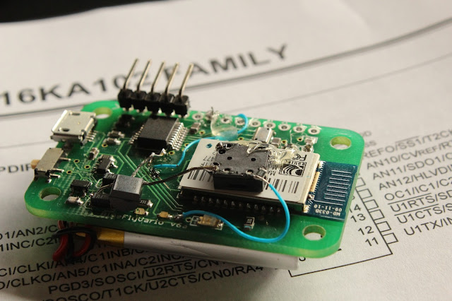
For those reasons I chose to consider electromagnetic buzzers. They have the advantage of being smaller, having good SMD options, having better frequency response in the range I am interested in, and able to be run at 3V effectively. The main disadvantage is the need for additional components including a switching transistor and a back EMF protection diode. Overall the additional component cost is less than $2. The buzzer I am probably going to use is listed here http://au.element14.com/jsp/search/productdetail.jsp?SKU=2135919. The one I have in the test bed at home appears as loud or louder than other audio only varios. See the picture below where I have hacked in a 8mm x 8 mm buzzer. I will need to tweak the PCB layout to make it all fit...
Power consumption changes a bit. I intend to ensure there is sufficient resistance in place for the buzzer so that power consumption is less than when connected via bluetooth, without negatively effecting the loudness. This should mean that battery life will still be well over 12 hours.
As part of this tinkering I have conducted a few tests of the latency associated with the transmission of data from the BlueFlyVario and time taken by Android to respond by beeping. My test setup, with a custom app and a test firmware on the vario, essentially beeped on the hardware, then sent a signal to the Android device saying beep as soon as you can. I recorded the output in Audacity to roughly measure the delay. It varied a little depending on the code order on both devices, but by far the biggest delay is the responsiveness of the audio subsystem on the Android device. I am using older Andriod code which adds over 100 ms of latency. Newer Andriod versions (4.1) and devices are targeting 10ms or less of latency. (http://createdigitalmusic.com/2012/07/android-high-performance-audio-in-4-1-and-what-it-means-plus-libpd-goodness-today/) But for the moment for most devices the total latency averages to 150ms, which is noticeable but probably not really significant for most pilots. However, it will be for some. This means that I think that some pilots will prefer the audio to be from the hardware rather than the Android device, even when connected via Bluetooth. More custom settings...
Oh, and finally, to support the hardware audio, I have implemented a Kalman filter on the PIC micro-controller This is going to be in the Android app as well to replace the relatively clumsy linear regression + IIR filter.
So, how will it work. Essentially, when you turn on the vario it will start in hardware audio mode. If you go up above the lift threshold it will start beeping, if you go down below the sink threshold it will sound the sink alarm. Like other advanced varios, the audio frequency changes dependent on the lift/sink rate. For example, for the lift settings, by default the audio frequency is 700 Hz at 0.0 m/s, then increases by 10 Hz for each 0.1 m/s. The cadence also decreases from 0.5s to about 0.25s as lift increases from 0.0 m/s to 3.0 m/s. When (if) the Bluetooth connection is made the hardware audio turns off and the connected device provides the audio. If no Bluetooth connection is made within about 5 minutes then the Bluetooth is turned off to save power.
Like most of what I do, I want the audio settings, and things like the Bluetooth scan period, to be configurable. I will do this by adding a few features to the Android app that sets features on the BlueFlyVario hardware audio mode.
I spent quite some time testing a range of buzzers. I started with piezo buzzers like everyone else. I 'drove' a few using the PWM (Output Compare) from the PIC. To do this I have had to alter my planned 6a layout to swap a few pins around. The main problem with piezo buzzers in my design is twofold. First, piezo buzzers are generally driven by a higher voltage than 3V in order for them to be loud. Adding a charge pump circuit is quite a big change that I am not going to make. Second, the resonant frequency is around 4000 Hz. They are not so loud at 700 Hz.
For those reasons I chose to consider electromagnetic buzzers. They have the advantage of being smaller, having good SMD options, having better frequency response in the range I am interested in, and able to be run at 3V effectively. The main disadvantage is the need for additional components including a switching transistor and a back EMF protection diode. Overall the additional component cost is less than $2. The buzzer I am probably going to use is listed here http://au.element14.com/jsp/search/productdetail.jsp?SKU=2135919. The one I have in the test bed at home appears as loud or louder than other audio only varios. See the picture below where I have hacked in a 8mm x 8 mm buzzer. I will need to tweak the PCB layout to make it all fit...

Power consumption changes a bit. I intend to ensure there is sufficient resistance in place for the buzzer so that power consumption is less than when connected via bluetooth, without negatively effecting the loudness. This should mean that battery life will still be well over 12 hours.
As part of this tinkering I have conducted a few tests of the latency associated with the transmission of data from the BlueFlyVario and time taken by Android to respond by beeping. My test setup, with a custom app and a test firmware on the vario, essentially beeped on the hardware, then sent a signal to the Android device saying beep as soon as you can. I recorded the output in Audacity to roughly measure the delay. It varied a little depending on the code order on both devices, but by far the biggest delay is the responsiveness of the audio subsystem on the Android device. I am using older Andriod code which adds over 100 ms of latency. Newer Andriod versions (4.1) and devices are targeting 10ms or less of latency. (http://createdigitalmusic.com/2012/07/android-high-performance-audio-in-4-1-and-what-it-means-plus-libpd-goodness-today/) But for the moment for most devices the total latency averages to 150ms, which is noticeable but probably not really significant for most pilots. However, it will be for some. This means that I think that some pilots will prefer the audio to be from the hardware rather than the Android device, even when connected via Bluetooth. More custom settings...
Oh, and finally, to support the hardware audio, I have implemented a Kalman filter on the PIC micro-controller This is going to be in the Android app as well to replace the relatively clumsy linear regression + IIR filter.


