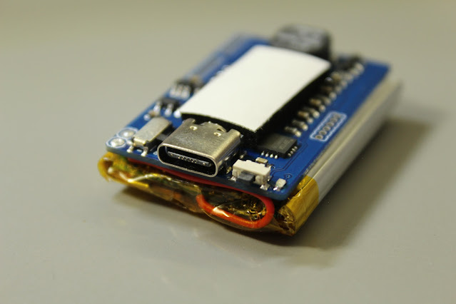
The new BlueFlyVario_Audio_v23 is the simplest and cheapest Bluefly. It is an audio only vario that is smaller and simpler than bluetooth models, but retains the same settings as its bigger brothers.
This vario is released in kit form and requires simple soldering of the battery to the circuit board for normal assembly.
What is in the bag?
 |
- The BlueFlyVario_Audio_v23 circuit board. This is 40mm x 27 mm and is sized to match the battery.
- A small piece of neoprene to protect the pressure sensor from light. Note that you should leave the white tape on it as shown in the assembly instruction below.
- A 900 mAh LiPo battery. This is the same battery used in the Bluetooth models of the vario. You will end up trimming the connector from the wires and soldering them to the circuit board.
Hardware Features
The BlueFlyVario_Audio_v23 features:
- The same sensitive pressure sensor, processor, and audio output of all of the v22 and v23 Blueflys.
- A USB-C interface (with attached FTDI serial port). This can be used to:
- Adjusting settings with the BFVDesktop
- Connect to apps such as XCTrack using a USB OTG cable.
- Charge the battery (if connected)
- Power the Bluefly (if no battery is connected)
- The same 900mAh battery as its bigger Bluetooth brothers (but with more life as it does not need to power bluetooth).
- Two buttons:
- The main button shown in the picture below above the USB-C port. This is used for normal powering on and off.
- The slide switch used for isolating the battery. Slide to the right is on. Use this for doing a hard reset, or fully powering down if you are not going to use the vario for months.
Note that although UART2, UART3, and SPI1 are exposed they are really only for advanced users who want to tinker.
The RST and GND pads shown in the top left work like other Bluefly models to perform a hardware reset (short them during startup).
Assembly Instructions
These instructions assume you are going to power the BlueFlyVario_Audio_v23 with the included battery. If you instead plan to power from USB directly see the note below.
Before you start get a feel for how the battery is matched with the board. Generally, I like have the printed side of the battery matched with the board, and run the wires along the board under the top edge of the battery as I think this fits neatest.
Start by sliding the battery isolator switch to the left so that when you solder the battery it does not start up before you are ready.
Next, cut the connector from the end of the battery wires. Strip the wires by a few mm, then solder the red wire to V_BAT and the black wire to GND. The secret to good soldering is to use flux, leaded solder, and clean with isopropanol. See the image below for how it should look.
To test it is working slide the battery isolator switch on and the vario should start. Press and hold the main switch for 3 seconds and it will turn off.
Next, place the battery on the base of the board. I like to secure it with some thin double sided tape to hold it in place. Notice the wires tucked under the end of the board and the neoprene in place to protect the pressure sensor.
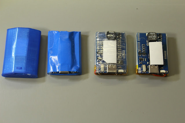
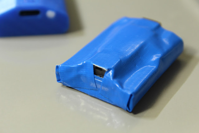
At this point you have a few options for how to enclose the vario. See below for a 3D printed case, blue tape, and clear tape options. You can download the files for the 3D printed case from thingverse. To print the case, lid and button your will need to have a 3D printer with pretty good tolerance and some skill using it as the parts are pretty fine. If you design a better case please share it with me.
A 3D printed case can be pretty tidy, but I actually prefer the simple tape method shown below. The overall size is smaller, and it is easier and quicker to hold everything together (and also easier to remove if you want to modify something). Make sure not to block the sound port of the speaker.
The primary purpose of the tape is to protect the battery from any physical damage while using the vario. You might like to include an extra layer around all parts of the battery just in case, as a damaged battery can be dangerous.
Alternate Power Options
You can also power the BlueFlyVario_Audio_v23 using the USB. You should only to this if you intend not to connect the battery. Close the USB PWR solder jumper with a dab of solder. When the USB-C port has power the Bluefly will start. Note that the slide switch has no effect, and also that the number of start-up beeps reflects that the input voltage is above 4.2V.
You could also power the vairo from an alternate source via V_BAT. Voltages from about 3.5V to about 5.5V should work. Below this range will not work, and above this range risks damaging the regulator.
Use
This is the simplest of Blueflys:
- Press the main button and the vario will start.
- It beeps when you are in lift :)
- Long press it for 3 seconds and it will shut down.
- Connect to the BFVDeskto application to adjust settings, although the defaults work for most pilots.


